
Compaq StorageWorks Data Replication Manager HSG80 ACS Version 8.5P Operations Guide

Configuring a Data Replication Manager Solution 4–15
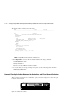
1. Connect a multi-mode, 50-micron fiber optic cable from port 1 of the top controller to
port 2 of the top Fibre Channel switch.
2. Connect a second multi-mode, 50-micron fiber optic cable from port 2 of the top
controller to port 4 of the top Fibre Channel switch.
3. Connect a third multi-mode, 50-micron fiber optic cable from port 1 of the bottom
controller to port 2 of the bottom Fibre Channel switch.
4. Connect a fourth multi-mode, 50-micron fiber optic cable from port 2 of bottom
controller to port 4 of the bottom Fibre Channel switch.
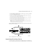
NOTE: You should see an illuminated green LED on the switch as soon as the cable is inserted
at both ends. This verifies that there is a good connection.
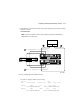
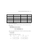
Figure 4–3 illustrates what your cabling should look like. The numbered callouts reflect
the steps that you just completed.
Figure 4–3. Cabling between the controllers and switches
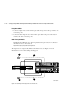
Connect the Target Site to the External Fiber Link
Locate the connection points at the target site that link the target site to the initiator site.
Look for either a fiber optic cable connector or a patch panel where you can insert a cable.
CXO7086A
1
2
3
4