
FW V06.XX/HAFM SW V08.02.00 HP StorageWorks Edge Switch 2/24 Service Manual (AA-RTDXC-TE, July 2004)


Diagnostics
88 Edge Switch 2/24 Service Manual
3
Is fault isolation being performed at the switch?
YES NO
↓ Fault isolation is being performed at the EWS interface or HAFM
appliance. Go to step 11.
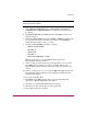
4
Ensure the switch reporting the problem is connected to facility AC power.
Inspect the switch for indications of being powered on, such as:
■ At the front bezel, an illuminated PWR LED (green) or ERR LED (amber).
■ Illuminated LEDs adjacent to Fibre Channel ports.
■ Audio emanations and airflow from cooling fans.
Does the switch appear powered on?
YES NO
↓ Both power supply modules failed or the CTP card failed. Go to
“MAP 0000: Start MAP” on page 32. If this is the second time at this
step and a dual power supply failure is ruled out, a CTP card failure is
indicated. Replace the switch. Exit MAP.
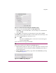
5
Inspect both power supply modules (with internal switch cooling fans) at the rear
of the switch.
Does inspection of a power supply and fan module (combined FRU) indicate a
failure? Indicators include:
■ The amber LED is illuminated on one or both power supplies.
■ One or more cooling fans are not rotating.
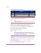
440 Embedded port hardware failed. Go to step 10.
810 High temperature warning (CTP thermal sensor). Go to step 9.
811 Critically hot temperature warning (CTP thermal
sensor).
Go to step 9.
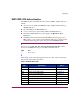
Table 9: MAP 500 Event Codes (Continued)
Event
Code
Explanation Action