
FW V06.XX/HAFM SW V08.02.00 HP StorageWorks Edge Switch 2/24 Service Manual (AA-RTDXC-TE, July 2004)


FRU Removal and Replacement
200 Edge Switch 2/24 Service Manual
Replacement
To replace a redundant power supply:
1. Remove the replacement power supply from its shipping container.
2. Inspect the rear of the power supply for bent or broken connector pins that
may have been damaged during shipping. If any pins are damaged, obtain a
new power supply.
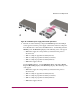
3. Position the power supply in the rear of the switch chassis as shown in part
(B) of Figure 56. Ensure the finger handles are disengaged and rotated 90
degrees outward.
a. While supporting the power supply with one hand, insert it into the switch
chassis.
b. Firmly push the power supply into the chassis. Rotate the finger handles
90 degrees inward to seat the power supply and engage the connector
pins. Ensure the faceplate is flush with the chassis cutout.
4. Connect the AC power cord to the power supply and to a facility power
source.
5. Wait several seconds, then inspect the power supply to ensure the amber LED
is extinguished. If the LED is illuminated, go to “MAP 0000: Start MAP” on
page 32 to isolate the problem.
6. Perform one of the following to inspect the Event Log:
If at a Web browser connected to the EWS interface, click the Log tab at the
Monitor panel. The Event Log displays. Ensure the following event codes
appear. If the event codes do not appear, go to “MAP 0000: Start MAP” on
page 32 to isolate the problem.
— 207–Power supply installed.
— 313–A cooling fan propeller has recovered (first fan).
— 314–A cooling fan propeller has recovered (second fan).
— 315–A cooling fan propeller has recovered (third fan).
— 203–Power supply AC voltage recovery.