
FW 08.01.00/HAFM SW 08.06.xx or later HP StorageWorks Edge Switch 2/24 Installation Guide (AA-RTDWE-TE, November 2005)


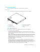

Table Of Contents
- Edge Switch 2/24 installation guide
- Contents
- Introduction to the Edge Switch 2/24
- Installing the Edge Switch
- Connecting the Edge Switch
- Edge Switch network addresses
- LAN-connecting the Edge Switch
- Setting up the HAFM appliance
- Using HAFM to configure the Edge Switch
- Setting the Edge Switch online and offline
- Configuring Edge Switch identification
- Configuring Edge Switch operating parameters
- Configuring fabric operating parameters
- Configuring switch binding
- Configuring preferred path
- Configuring ports
- Configuring SNMP trap message recipients
- Configuring, enabling, and testing e-mail notification
- Configuring and enabling call-home features
- Configuring and enabling Ethernet events
- Configuring, enabling, and testing call-home event notification
- Threshold alerts
- Creating new alerts
- Figure 30 Configure Threshold Alerts dialog box
- Figure 31 New Threshold Alerts dialog box-first screen
- Figure 32 New Threshold Alerts dialog box-second screen
- Figure 33 New Threshold Alerts dialog box-third screen
- Figure 34 New Threshold Alerts dialog box-summary screen
- Figure 35 Configure Threshold Alerts dialog box-alert activated
- Modifying alerts
- Activating or deactivating alerts
- Deleting alerts
- Creating new alerts
- Configuring SANtegrity Authentication
- Backing up HAFM configuration data
- Resetting configuration data
- Enabling the HAFM Basic interface
- Enabling Telnet
- Connecting the Edge Switch to a fabric
- Using the HAFM Basic interface
- Launching the HAFM Basic interface
- Setting the Edge Switch offline and online
- Configuring Edge Switch ports
- Configuring BB credit
- Configuring Edge Switch identification
- Configuring date and time
- Configuring Edge Switch parameters
- Configuring network information
- Configuring SNMP trap message recipients
- Enabling or disabling the CLI
- Configuring zoning
- Managing firmware versions
- Regulatory compliance and safety
- Technical specifications
- Index
Edge Switch 2/24 installation guide 19
Rear panel
Figure 2 shows the rear of the Edge Switch and identifies its components.
Figure 2 Edge Switch (rear view)
The rear panel of the Edge Switch includes the following:
• Power supplies
The Edge Switch contains two power supply assemblies . The redundant, load-sharing power
supply assemblies step down and rectify facility input power to provide 3.3 volts direct current
(VDC), 5 VDC, and 12 VDC to the CTP card. The power supplies also provide input filtering,
overvoltage protection, and overcurrent protection.
Either power supply can be replaced while the Edge Switch is operational. Each power supply
has a separate connection to the CTP card to allow for independent AC power sources. The
power supplies are input rated at 90 to 264 volts alternating current (VAC). Power supply
requirements are listed in ”Technical specifications” on page 115.)
• Cooling fans
Three cooling fans integrated in each power supply assembly (a total of six fans) provide cooling
for the power supplies and CTP card, as well as redundancy for continued operation if a single
fan fails.
• Maintenance port
The rear panel provides a 9-pin RS-232 maintenance port that provides a connection for a local
terminal or dial-in connection for a remote terminal. Although the port is typically used by
authorized maintenance personnel, operations personnel can use the port to configure Edge
Switch network addresses.
1 Power supplies with internal
cooling fans (2)
2 Maintenance port
SHR 2596A
1
2