
FW 08.01.00/HAFM SW 08.06.xx or later HP StorageWorks Edge Switch 2/24 Installation Guide (AA-RTDWE-TE, November 2005)


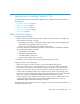


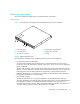

Table Of Contents
- Edge Switch 2/24 installation guide
- Contents
- Introduction to the Edge Switch 2/24
- Installing the Edge Switch
- Connecting the Edge Switch
- Edge Switch network addresses
- LAN-connecting the Edge Switch
- Setting up the HAFM appliance
- Using HAFM to configure the Edge Switch
- Setting the Edge Switch online and offline
- Configuring Edge Switch identification
- Configuring Edge Switch operating parameters
- Configuring fabric operating parameters
- Configuring switch binding
- Configuring preferred path
- Configuring ports
- Configuring SNMP trap message recipients
- Configuring, enabling, and testing e-mail notification
- Configuring and enabling call-home features
- Configuring and enabling Ethernet events
- Configuring, enabling, and testing call-home event notification
- Threshold alerts
- Creating new alerts
- Figure 30 Configure Threshold Alerts dialog box
- Figure 31 New Threshold Alerts dialog box-first screen
- Figure 32 New Threshold Alerts dialog box-second screen
- Figure 33 New Threshold Alerts dialog box-third screen
- Figure 34 New Threshold Alerts dialog box-summary screen
- Figure 35 Configure Threshold Alerts dialog box-alert activated
- Modifying alerts
- Activating or deactivating alerts
- Deleting alerts
- Creating new alerts
- Configuring SANtegrity Authentication
- Backing up HAFM configuration data
- Resetting configuration data
- Enabling the HAFM Basic interface
- Enabling Telnet
- Connecting the Edge Switch to a fabric
- Using the HAFM Basic interface
- Launching the HAFM Basic interface
- Setting the Edge Switch offline and online
- Configuring Edge Switch ports
- Configuring BB credit
- Configuring Edge Switch identification
- Configuring date and time
- Configuring Edge Switch parameters
- Configuring network information
- Configuring SNMP trap message recipients
- Enabling or disabling the CLI
- Configuring zoning
- Managing firmware versions
- Regulatory compliance and safety
- Technical specifications
- Index
Edge Switch 2/24 installation guide 17
Hardware components
This section describes the Edge Switch 2/24 main hardware components.
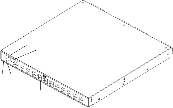
Front panel
Figure 1 shows the front of the Edge Switch and identifies the front panel components.
Figure 1 Edge Switch (front view)
The front panel of the Edge Switch includes the following connectors and indicators:
• Power (green) and Error (amber) LEDs
The Power LED illuminates when the Edge Switch is connected to facility AC power and is
powered on. If the LED extinguishes, a facility power source, power cord, or power distribution
failure is indicated.
The Error LED illuminates when the Edge Switch detects an event requiring immediate operator
attention, such as a FRU failure. The LED remains illuminated as long as an event is active. The
LED extinguishes when the Clear System Error Light function is selected from the Element
Manager. The LED blinks if unit beaconing is enabled. An illuminated Error LED (indicating a
failure) takes precedence over unit beaconing.
• Ethernet LAN connector
The Ethernet LAN connector is a 10/100 megabit per second (Mbps) RJ-45 twisted-pair
connector that attaches to an Ethernet LAN to provide communication with the HAFM appliance,
the HAFM Basic interface, or an SNMP management workstation. Two green LEDs are
associated with the LAN connector. When illuminated, the left LED indicates LAN operation at
10 Mbps, and the right LED indicates LAN operation at 100 Mbps.
1 Power LED (green)
2 Error LED (amber)
3 Ethernet LAN connector
4 Initial machine load (IML) button
5 SFP fiber optic connectors
6 Port LEDs
3
4
1
2
5
6