
FW 08.01.00 McDATA Sphereon 4500 Fabric Switch Installation and Service Manual (620-000159-330, November 2005)

2
Installation Tasks
2-35
Installation Tasks
b. Connect the remaining end of the Ethernet cable to the LAN:
• If the server is installed on a customer-supplied LAN
segment, connect the cable to the LAN as directed.
• If the server is installed through the Ethernet hub, connect
the cable to any available hub port.
5. If required, connect the server to the customer intranet
(public LAN interface):
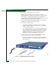
a. As shown in Figure 2-16, connect one end of a customer-
supplied Ethernet patch cable to the left RJ-45 adapter (LAN 1)
at the rear of the server.
b. Connect the remaining end of the Ethernet cable to the
corporate intranet as directed by the customer.
6. As shown in Figure 2-16, connect a phone cord to the left RJ-11
adapter (LINE) at the rear of the server and a facility telephone
connection.
7. As shown in Figure 2-16, connect the AC power cord to the server
and a facility power source or rack power strip that provides
single-phase, 90 to 264 VAC current.
8. When the power cord is connected, the server powers on and
performs power-on self-tests (POSTs). During POSTs:
a. The green liquid crystal display (LCD) panel illuminates.
b. The green hard disk drive (HDD) LED blinks momentarily,
and processor speed and random-access memory information
display momentarily at the LCD panel.
c. After a few seconds, LCD panel displays a Boot from LAN?
Press <Enter> message.
d. Ignore the message. After ten seconds, the server performs the
boot sequence from the basic input/output system (BIOS).
After successful boot and POST completion, the LCD panel
displays a Welcome!! message.
e. The server then continuously cycles through and displays
operational information at the LCD panel.
9. Press the left edge (PUSH label) of the LCD panel to disengage
the panel and expose the CD-RW drive. Insert a blank rewritable
CD into the CD-RW drive and close the panel.