
FW 08.01.00 McDATA Sphereon 4500 Fabric Switch Installation and Service Manual (620-000159-330, November 2005)

2
2-10
McDATA Sphereon 4500 Fabric Switch Installation and Service Manual
Installation Tasks
9. Perform one of the following:
— If the switch is to be managed through the EFCM Basic Edition
interface, go to Task 4: Configure Product at the EFCM Basic
Edition Interface (Optional).
— If the switch is to be managed through a management or
customer-supplied server, go to Task 5: Configure Product
Network Information (Optional).
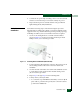
Rack-Mount
Installation
Perform the following steps to install and configure the switch in a
Fabricenter cabinet or a customer-supplied equipment rack. An
optional rack-mount kit, T10 Torx tool, and #2 Phillips screwdriver
are required.
1. Locate the rack-mount position as directed by the customer. The
switch is 1.75 inches, or 1U high.
2. Verify all FRUs are installed as ordered.
3. Open the rack-mount kit and inspect the contents. Refer to the
enclosed bill of materials and verify all parts are delivered.
4. Using a T10 Torx tool and #2 Phillips screwdriver, install the
switch in the equipment cabinet. Refer to McDATA Sphereon 4300,
4500, and 4700 Switch Rack-Mount Kit Installation Instructions
(958-000316) for guidance.
5. Connect both AC power cords to receptacles at the rear of the
chassis.
6. Connect AC power cords to separate (for redundancy) rack
power strips connected to a facility power source that provides
single-phase, 100 to 240 VAC current.
7. When the first power cord is connected, the switch powers on and
performs POSTs. During POSTs:
a. The green power (PWR) LED on the front panel illuminates.
b. The amber system error (ERR) LED on the front panel blinks
momentarily while the switch is tested.
c. The green LED associated with the Ethernet port blinks
momentarily while the port is tested.
d. LEDs associated with Fibre Channel ports blink momentarily
while the ports are tested.