
FW 08.01.00 McDATA Sphereon 4500 Fabric Switch Installation and Service Manual (620-000159-330, November 2005)

Removal and Replacement Procedures
5-9
Removal and Replacement Procedures
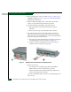
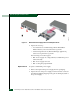
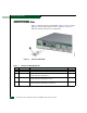
3. Position the power supply in the rear of the switch as shown in
part (2) of Figure 5-2. Ensure the finger handles are disengaged
and rotated 90 degrees outward.
a. While supporting the power supply with one hand, insert it
into the switch chassis.
b. Firmly push the power supply into the chassis. Rotate the
finger handles 90 degrees inward to seat the power supply and
engage the connector pins. Ensure the faceplate is flush with
the chassis cutout.
4. Connect the AC power cord to the power supply and a facility
power source.
5. Wait several seconds, then inspect the power supply to ensure the
amber LED extinguishes. If the LED illuminates, go to MAP 0000:
Start MAP to isolate the problem.
6. Inspect the Event Log:
— At a web browser communicating with the EFCM Basic
Edition interface, select Event from the Logs menu.
— At the management server (Element Manager application),
select Event Log from the Logs menu.
Ensure the following event codes appear:
• 203 - Power supply AC voltage recovery.
• 207 - Power supply installed.
• 315 - Cooling fan propeller recovered.
If the event codes do not appear, go to MAP 0000: Start MAP to
isolate the problem.
7. Verify power supply operation. At a web browser communicating
with the EFCM Basic Edition interface or at the management
server (Element Manager application), open the Hardware View
and observe the FRU graphic to ensure alert symbols do not
appear (yellow triangle or red diamond).
If a problem is indicated, go to MAP 0000: Start MAP to isolate the
problem.
8. Perform a data collection procedure. Refer to Collect Maintenance
Data (EFCM Basic Edition) or Collect Maintenance Data (SAN
management application) for instructions.