
FW 08.01.00 McDATA Sphereon 4500 Fabric Switch Installation and Service Manual (620-000159-330, November 2005)

Removal and Replacement Procedures
5-7
Removal and Replacement Procedures
RRP 2: Redundant Power Supply
Use the following procedures to remove or replace a redundant
power supply. A list of required tools is provided.
Tools Required A door key with 5/16-inch socket (provided with the FC-512
Fabricenter equipment cabinet) is required.
Removal To remove a redundant power supply:
1. If the product is not rack-mounted, go to step 2. If the product is
rack-mounted, perform one of the following:
— If the product is installed in an FC-512 Fabricenter equipment
cabinet, insert the 5/16-inch door tool into the socket hole at
the right top of the door (front or rear). Turn the tool counter-
clockwise to unlock and open the door.
— If the product is installed in a customer-supplied equipment
cabinet, unlock and open the cabinet door (front or rear) as
directed by the customer representative.
2. Identify the defective power supply from:
— The illuminated amber LED on the FRU.
— At a web browser communicating with the EFCM Basic
Edition interface or at the management server (Element
Manager application), FRU failure information displayed at
the Hardware View, FRU List View, or Event Log.
3. Disconnect the power cord from the power supply.
DANGER
Disconnect the power cords.
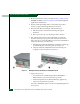
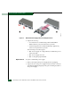
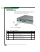
4. Disengage and remove the power supply:
a. Disengage the locking mechanism by rotating both finger
handles outward 90 degrees as shown in part (1) of Figure 5-2.
b. Use the finger handles to pull the power supply out of the
switch chassis as shown in part (2) of Figure 5-2. Support the
power supply as it is pulled from the chassis.