
FW 08.01.00 McDATA Sphereon 4500 Fabric Switch Installation and Service Manual (620-000159-330, November 2005)

Maintenance Analysis Procedures
3-11
Maintenence Analysis Procedures
MAP 0100: Power Distribution Analysis
This MAP describes fault isolation for the product power distribution
system, including defective AC power cords or redundant power
supplies. The failure indicator is:
• Failure of the product to power on.
• Event code 200 or 201 observed at the Event Log (EFCM Basic
Edition or Element Manager interface).
1
Ensure the product is connected to facility power. Inspect the product
for indications of being powered on, such as:
• An illuminated PWR LED (green) or ERR LED (amber).
• Illuminated LEDs adjacent to Fibre Channel ports.
• Audio emanations and airflow from cooling fans.
Is the product powered on?
YES NO
↓ A power distribution problem is indicated. Go to step 4.
2
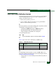
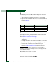
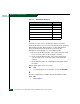
Ta bl e 3 -4 lists event codes, explanations, and MAP steps.
3
As indicated by visual inspection or event code 200 or 201, one or
both power supplies failed and must be removed and replaced. Refer
to RRP 2: Redundant Power Supply.
• The procedure is concurrent and performed while the product is
operational.
Table 3-4 MAP 100 Event Codes
Event
Code
Explanation Action
200 Power supply AC voltage failure. Go to step 3.
201 Power supply DC voltage failure. Go to step 3.