
FW 07.00.00/HAFM SW 08.06.00 McDATA Sphereon 4500 Fabric Switch Installation and Service Manual (620-000159-320, April 2005)

2
2-12
McDATA Sphereon 4500 Fabric Switch Installation and Service Manual
Installation Tasks
7. After successful POST completion, the green power (PWR) LED
remains illuminated and all other front panel LEDs extinguish.
8. If a POST error or other malfunction occurs, go to MAP 0000: Start
MAP on page 3-6 to isolate the problem.
9. Perform one of the following steps:
— If the switch is to be managed through the SANpilot interface,
go to Task 4: Configure the Switch at the SANpilot Interface
(Optional) on page 2-13.
— If the switch is to be managed through the management server
or a customer-supplied server, go to Task 5: Configure Switch
Network Information (Optional) on page 2-41.
Rack-Mount
Installation
Perform the following steps to install and configure the switch in a
Fabricenter equipment cabinet or a customer-supplied equipment
rack. An optional rack-mount kit, T10 Torx tool, and #2 Phillips
screwdriver are required.
1. Locate the rack-mount position as directed by the customer. The
switch is 1.75 inches, or 1U high.
2. Verify all FRUs, including SFP optical transceivers and combined
cooling fan and power supply assemblies are installed as ordered.
3. Open the rack-mount kit and inspect the contents. Refer to the
enclosed bill of materials and verify all parts are delivered.
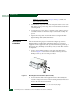
4. Using a T10 Torx tool and #2 Phillips screwdriver, install the
switch in the equipment cabinet. Refer to Sphereon 4500 Switch
Rack-Mount Kit Installation Instructions (958-000267) for guidance.
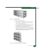
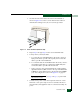
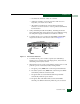
5. Connect both AC power cords to the right (PS0) and left (PS1)
receptacles at the rear of the chassis as shown in Figure 2-5 on
page 2-11.
6. Connect both AC power cords to separate (for redundancy)
facility power sources that provide single-phase, 100 to 240 VAC
current.
7. When the first power cord is connected, the switch powers on and
performs POSTs. During POSTs: