
FW 07.00.00/HAFM SW 08.06.00 McDATA Sphereon 4500 Fabric Switch Installation and Service Manual (620-000159-320, April 2005)

2
Installation Tasks
2-11
Installation Tasks
— Grounded AC electrical outlets are available.
— Adequate ventilation is present, and areas with excessive
heat, dust, or moisture are avoided.
— All planning considerations are met. Refer to McDATA
Products in a SAN Environment - Planning Manual (620-000124)
for information.
3. Verify all field-replaceable units (FRUs), including small form
factor pluggable (SFP) optical transceivers and combined cooling
fan and power supply assemblies are installed as ordered.
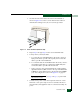
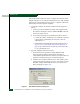
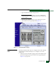
4. Connect both AC power cords to the right (PS0) and left (PS1)
receptacles at the rear of the chassis as shown in Figure 2-5.
Figure 2-5 AC Power Connections
5. Connect both AC power cords to separate (for redundancy)
facility power sources that provide single-phase, 100 to 240 volt
alternating current (VAC) current.
6. When the first power cord is connected, the switch powers on and
performs power-on self-tests (POSTs). During POSTs:
a. The green power (PWR) LED on the front panel illuminates.
b. The amber system error (ERR) LED on the front panel blinks
momentarily while the switch is tested.
c. The green LED associated with the Ethernet port blinks
momentarily while the port is tested.
d. The green/blue and amber LEDs associated with Fibre
Channel ports blink momentarily while the ports are tested.
PS0
Connector
PS1
Connector