
FW 07.00.00/HAFM SW 08.06.00 McDATA Sphereon 4500 Fabric Switch Installation and Service Manual (620-000159-320, April 2005)

1
1-6
McDATA Sphereon 4500 Fabric Switch Installation and Service Manual
General Information
IML/Reset Button
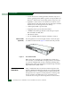
When the IML/RESET button (Figure 1-2 on page 1-3) is pressed,
held for three seconds, and released, the switch performs an IML that
reloads the firmware from FLASH memory. This operation is not
disruptive to Fibre Channel traffic. If the button is held for more than
three seconds, the ERR LED blinks at twice the unit beaoning rate.
When the IML/RESET button is pressed and held for ten seconds, the
switch performs a reset. After three seconds, the ERR LED blinks at
twice the unit beaoning rate. A reset is disruptive and resets the:
• Microprocessor and functional logic for the CTP card and reloads
the firmware from FLASH memory.
• Ethernet LAN interface, causing the connection to the
management server to drop momentarily until the connection
automatically recovers.
• Ports, causing all Fibre Channel connections to drop momentarily
until the connections automatically recover. This causes attached
devices to log out and log back in, therefore data frames lost
during switch reset must be retransmitted.
A reset should only be performed if a CTP card failure is indicated.
As a precaution, the IML/RESET button is flush mounted to protect
against inadvertent activation.
Ethernet LAN
Connector
The front panel provides a 10/100 megabit per second (Mbps) RJ-45
twisted-pair connector (Figure 1-2 on page 1-3) that attaches to an
Ethernet LAN to provide communication with the management
server or a simple network management protocol (SNMP)
management workstation. The connector provides two green LEDs.
The left LED illuminates to indicate LAN operation at 10 Mbps, while
the right LED illuminates to indicate LAN operation at 100 Mbps.
Power and System
Error LEDs
The PWR LED (Figure 1-2 on page 1-3) illuminates when the switch
is connected to facility AC power and is operational (the switch does
not have a power switch). If the LED extinguishes, a facility power
source, power cord, or power distribution failure is indicated.
The ERR LED (Figure 1-2 on page 1-3) illuminates when the switch
detects an event requiring immediate operator attention, such as a
FRU failure. The LED remains illuminated as long as an event is
active. The LED extinguishes when Clear System Error Light is selected
from the SANpilot interface or Element Manager application.