
FW 07.00.00/HAFM SW 08.06.00 McDATA Sphereon 4500 Fabric Switch Installation and Service Manual (620-000159-320, April 2005)

3-78
McDATA Sphereon 4500 Fabric Switch Installation and Service Manual
• At the front bezel, an illuminated PWR LED (green)
or ERR LED (amber).
• Illuminated LEDs adjacent to Fibre Channel ports.
• Audio emanations and airflow from cooling fans.
Does the switch appear powered on?
YES NO
↓ Analysis for an Ethernet link, AC power distribution, or CTP
failure is not described in this MAP. Go to MAP 0000: Start
MAP on page 3-6. If this is the second time at this step,
contact the next level of support. Exit MAP.
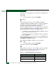
11
Inspect Fibre Channel port operational states at the SANpilot
interface.
a. At the View panel, click the Port Properties tab. The View panel
(Port Properties tab) displays with port 0 highlighted in red.
b. Click the port number (0 through (23) for which a failure is
suspected to display properties for that port.
c. Inspect the Operational State field. Scroll down the View panel
as necessary.
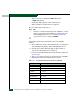
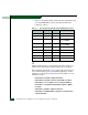
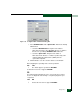
d. Table 3-10 on page 3-78 lists port operational states and MAP
0600 steps that describe fault isolation procedures.
Table 3-10 Port Operational States and Actions (SANpilot)
Operational State Action
Offline Go to step 19.
Not Operational Go to step 19.
Port Failure Go to step 6.
Testing Internal or external loopback test in process. Exit MAP.
Invalid Attachment Go to step 22.
Link Reset Go to step 33.
Not Installed Go to step 12.