
FW 07.00.00/HAFM SW 08.06.00 McDATA Sphereon 4500 Fabric Switch Installation and Service Manual (620-000159-320, April 2005)

3-74
McDATA Sphereon 4500 Fabric Switch Installation and Service Manual
NO YES
↓ A fan module failure is indicated. Go to step 6.
17
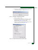
At the Hardware View, does a grey square appear at the alert panel,
a No Link status appear at the Sphereon 4500 Status table, and
graphical FRUs appear uninstalled?
YES NO
↓ A green circle appears at the alert panel and the switch
appears operational. Exit MAP.
The grey square indicates the management server or customer-
supplied server cannot communicate with the switch because:
• The switch-to-server Ethernet link failed.
• AC power distribution in the switch failed, or AC power was
disconnected.
• The switch CTP card failed.
Go to MAP 0000: Start MAP on page 3-6. If this is the second time at
this step and an Ethernet link or AC power distribution failure is ruled
out, a CTP card failure is indicated. Replace the switch. Exit MAP.
MAP 0600: Port Failure and Link Incident Analysis
This MAP describes fault isolation for shortwave laser small form
factor pluggable (SFP) optical transceivers, longwave laser SFP
optical transceivers, and Fibre Channel link incidents. Failure
indicators include:
• An event code recorded at the SANpilot event log or Sphereon
4500 Event Log (management server).
• A link incident event code recorded at the console of an OSI
server attached to the switch reporting the problem.
• One or more amber LEDs on the ports illuminate.
• A port operational state message or a Failed message associated
with a port at the SANpilot interface.
• One or more emulated amber LEDs on a port graphic at the
Hardware View illuminate.