
FW 07.00.00/HAFM SW 08.06.00 McDATA Sphereon 4500 Fabric Switch Installation and Service Manual (620-000159-320, April 2005)

3-68
McDATA Sphereon 4500 Fabric Switch Installation and Service Manual
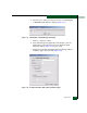
f. Type a switch description in the Description field.
g. Type the switch IP address (determined by the customer’s
network administrator) in the IP Address field.
h. Type the switch subnet mask (determined by the customer’s
network administrator) in the Subnet Mask field.
i. At the Data Source for Domain area of the dialog box, select the
Use auto detection, Use the server, or Use a specific RDC radio
button (determined by the customer’s network administrator).
j. Click OK to save the entered information, close the dialog box,
and define the new product configuration to the SAN
management application.
k. Click OK to close the Discover Setup dialog box and return to the
SAN management application.
At the SAN management application master log, did the IP address
associated with the switch change to the new product configuration
and did the Ethernet connection recover?
NO YES
↓ The switch-to-server connection is restored and appears
operational. Exit MAP.
Contact the next level of support. Exit MAP.
MAP 0500: FRU Failure Analysis
This MAP describes fault isolation for the switch and FRUs. Failure
indicators include:
• An event code recorded at the SANpilot event log or Sphereon
4500 Event Log (management server).
• The amber LED on the FRU illuminates.
•A Failed message associated with a FRU at the SANpilot
interface.
• The amber emulated LED on a power supply at the Hardware
View illuminates.
• A blinking red and yellow diamond (failed FRU indicator)
appears over a FRU graphic; or a grey square (status unknown
indicator) or yellow triangle (attention indicator) appears at the
alert panel of the Hardware View.