
FW 07.00.00/HAFM SW 08.06.00 McDATA Sphereon 4500 Fabric Switch Installation and Service Manual (620-000159-320, April 2005)


3-54
McDATA Sphereon 4500 Fabric Switch Installation and Service Manual
8
Ensure the switch reporting the problem is connected to facility AC
power. Inspect the switch for indications of being powered on, such
as:
• At the front bezel, an illuminated PWR LED (green)
or ERR LED (amber).
• Illuminated LEDs adjacent to Fibre Channel ports.
• Audio emanations and airflow from cooling fans.
Does the switch appear powered on?
YES NO
↓ A power distribution problem is indicated. Go to MAP 0100:
Power Distribution Analysis on page 3-30. Exit MAP.
9
At the front of the switch, inspect the amber ERR LED.
Is the LED illuminated?
NO YES
↓ A FRU failure or link incident is indicated. Go to MAP 0000:
Start MAP on page 3-6. Exit MAP.
10
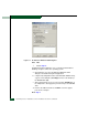
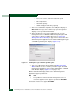
The switch-to-server Ethernet link failed. At the physical map, right-
click the icon with the grey square and exclamation mark representing
the switch reporting the problem. A pop-up menu appears. Select the
Element Manager option from the menu. The Element Manager
application opens and the Hardware View (Figure 3-10 on page 3-20)
displays. At the Hardware View:
• A grey square appears at the alert panel.
• No FRUs are visible for the switch.
• The Sphereon 4500 Status table is yellow, the Status field
displays No Link, and the Reason field displays an error
message.
Table 3-7 on page 3-55 lists the error messages and associated steps
that describe fault isolation procedures.