
FW 07.00.00/HAFM SW 08.06.00 HP StorageWorks Edge Switch 2/24 Installation Guide (AA-RTDWD-TE/958-000283-003, March 2005)


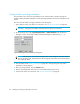


Table Of Contents
- Edge Switch 2/24 installation guide
- Contents
- Switch features
- Installing and configuring the Edge Switch 2/24
- Installation options
- Review installation requirements
- Unpack and Inspect the switch
- Install the Edge Switch on a desktop
- Install the Edge Switch in a rack
- Configure switch network information
- LAN-Connect the switch
- Configure the HAFM appliance
- Frequently used HAFM settings
- Set the switch online
- Set the switch offline
- Configure switch identification
- Configure switch operating parameters
- Configure fabric operating parameters
- Configure switch binding
- Configure SNMP trap message recipients
- Configure, enable, and test e-mail notification
- Configure and enable Ethernet events
- Configure call home event notification
- Configure threshold alerts
- Create new alerts
- Figure 25 Configure Threshold Alerts dialog box
- Figure 26 New Threshold Alerts dialog box-first screen
- Figure 27 New Threshold Alerts dialog box-second screen
- Figure 28 New Threshold Alerts dialog box-third screen
- Figure 29 New Threshold Alerts dialog box-summary screen
- Figure 30 Configure Threshold Alerts dialog box-alert activated
- Modify alerts
- Activate or deactivate alerts
- Delete alerts
- Create new alerts
- Configure SANtegrity authentication
- Back up HAFM configuration data
- Configure open systems management appliance
- Configure feature key
- Configure Open Trunking
- Enable Embedded Web Server
- Enable Telnet
- Connect cables to Fibre Channel ports
- Connect the switch to a fabric
- Unpack, inspect, and install the ethernet hub (optional)
- Using HAFM from a remote location
- Using the Embedded Web Server
- Manage firmware versions
- Regulatory compliance and safety
- Technical specifications
- Index

Installing and configuring the Edge Switch 2/2450
At least one switch in a multiswitch fabric needs to be set as Principal or Default. If all of the switches
are set to Never Principal, all of the interswitch links (ISLs) will segment. If all but one switch is set to
Never Principal and the switch that was principal goes offline, then all of the other ISLs will segment.
NOTE: HP recommends that you leave the switch priority setting as Default. If you are considering
setting this value to something other than default, refer to the section on principal switch selection for
multiswitch fabrics in the HP StorageWorks SAN High Availability planning guide for details.
In, for example, the audit log, you may notice that the Principal setting maps to a number code of 1,
Default maps to a number code of 254, and Never Principal maps to a number code of 255. The
number codes of 2-253 are not currently in use.
Interop Mode
Select one of the following options:
• Homogeneous Fabric—Select this mode if the fabric contains only HP directors and switches that
are operating in Homogeneous Fabric mode.
• Open Fabric 1.0—Default. Select this mode if the fabric contains HP directors and switches, as
well as other open-fabric compliant switches. Select this mode for managing heterogeneous
fabrics.
Configure switch binding
This feature is managed through the Switch Binding submenu options available on the Element
Manager Configure menu. Using Switch Binding, you can specify devices and switches that can
attach to director and switch ports. This provides security in environments that include a large
number of devices by ensuring that only the intended set of devices attach to a switch or director.
For complete procedures on configuring this optional feature, refer to HP StorageWorks Edge Switch
Element Manager user guide.
The preferred path feature lets you specify and configure one or more ISL data paths between
multiple directors or switches in a fabric. Each participating director or switch must be configured as
part of a desired path. The following rules apply when configuring a preferred path:
• The switch domain ID must be set to Insistent. For instructions, refer to ”Configure switch
operating parameters” on page 45.
• Domain IDs range between 1 through 31.
• Source and exit port numbers are limited to the range of ports available on the switch
(0 through 23).
• For each source port, only one path is defined to each destination domain ID.
NOTE: Activating a preferred path can result in receipt of out-of- order frames if the
preferred path differs from the current path, if input and output (I/O) is active from the source
port, and if congestions is present on the current path.