
FW 07.00.00/HAFM SW 08.06.00 HP StorageWorks Edge Switch 2/24 Installation Guide (AA-RTDWD-TE/958-000283-003, March 2005)


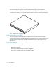


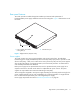

Table Of Contents
- Edge Switch 2/24 installation guide
- Contents
- Switch features
- Installing and configuring the Edge Switch 2/24
- Installation options
- Review installation requirements
- Unpack and Inspect the switch
- Install the Edge Switch on a desktop
- Install the Edge Switch in a rack
- Configure switch network information
- LAN-Connect the switch
- Configure the HAFM appliance
- Frequently used HAFM settings
- Set the switch online
- Set the switch offline
- Configure switch identification
- Configure switch operating parameters
- Configure fabric operating parameters
- Configure switch binding
- Configure SNMP trap message recipients
- Configure, enable, and test e-mail notification
- Configure and enable Ethernet events
- Configure call home event notification
- Configure threshold alerts
- Create new alerts
- Figure 25 Configure Threshold Alerts dialog box
- Figure 26 New Threshold Alerts dialog box-first screen
- Figure 27 New Threshold Alerts dialog box-second screen
- Figure 28 New Threshold Alerts dialog box-third screen
- Figure 29 New Threshold Alerts dialog box-summary screen
- Figure 30 Configure Threshold Alerts dialog box-alert activated
- Modify alerts
- Activate or deactivate alerts
- Delete alerts
- Create new alerts
- Configure SANtegrity authentication
- Back up HAFM configuration data
- Configure open systems management appliance
- Configure feature key
- Configure Open Trunking
- Enable Embedded Web Server
- Enable Telnet
- Connect cables to Fibre Channel ports
- Connect the switch to a fabric
- Unpack, inspect, and install the ethernet hub (optional)
- Using HAFM from a remote location
- Using the Embedded Web Server
- Manage firmware versions
- Regulatory compliance and safety
- Technical specifications
- Index

Edge Switch 2/24 installation guide 17
Rear panel features
The switch provides a modular design that enables quick removal and replacement of
field-replaceable power supply assemblies with internal cooling fans. Figure 3 illustrates the rear of
the switch.
Figure 3 Edge Switch 2/24 (rear view)
Power supplies
The switch contains two power supply assemblies with internal cooling fans. The redundant,
load-sharing power supply assemblies step down and rectify facility input power to provide 3.3 volts
direct current (VDC), 5 VDC, and 12 VDC to the control processor (CTP) card. The power supplies
also provide input filtering, overvoltage protection, and overcurrent protection. An amber LED on
each assembly illuminates if the FRU fails.
Either power supply can be replaced while the switch is operational. Each power supply has a
separate connection to the CTP card to allow for independent AC power sources. The power
supplies are input rated at 90 to 264 volts alternating current (VAC).
Three cooling fans integrated in each power supply assembly (six fans total) provide cooling for the
power supplies and CTP card, as well as redundancy for continued operation if a single fan fails.
Fans are removed and replaced as part of the integrated power supply.
Power supply requirements are listed in ”Technical specifications” on page 95.
1 Power supplies with internal
cooling fans (2)
2 Maintenance port
1
2