
FW 07.00.00/HAFM SW 08.06.00 McDATA Sphereon 4300 Fabric Switch Installation and Service Manual (620-000171-010, April 2005)


2
Installation Tasks
2-5
Installation Tasks
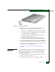
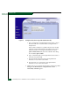
Figure 2-1 AC Power Connection
6. When the power cord is connected, the switch powers on and
performs power-on self-tests (POSTs). During POSTs:
a. The green power (PWR) LED on the front panel illuminates.
b. The amber system error (ERR) LED on the front panel blinks
momentarily while the switch is tested.
c. The green LED associated with the Ethernet port blinks
momentarily while the port is tested.
d. The green/blue and amber LEDs associated with Fibre
Channel ports blink momentarily while the ports are tested.
7. After successful POST completion, the green power (PWR) LED
remains illuminated and all other front panel LEDs extinguish.
8. If a POST error or other malfunction occurs, go to MAP 0000: Start
MAP on page 3-6 to isolate the problem.
9. Go to Task 3: Configure the Switch at the SANpilot Interface on
page 2-6.
Rack-Mount
Installation
Perform the following steps to install and configure the switch in a
Fabricenter equipment cabinet or a customer-supplied equipment
rack. An optional rack-mount kit, T10 Torx tool, and #2 Phillips
screwdriver are required.
1. Locate the rack-mount position as directed by the customer. The
switch is 1.75 inches, or 1U high.
2. Verify all SFP optical transceivers are installed as ordered.