
HP StorageWorks HSG80 ACS Solution Software V8.8 for Linux X86 Installation and Configuration Guide (AA-RV1LA-TE, March 2005)


Planning a Subsystem
31HSG80 ACS Solution Software V8.8 for Linux X86 Installation and Configuration Guide
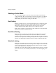
What is Failover Mode?
Failover is a way to keep the storage array available to the host if one of the
controllers becomes unresponsive. A controller can become unresponsive because
of a controller hardware failure. Failover keeps the storage array available to the
hosts by allowing the surviving controller to take over total control of the
subsystem.
Transparent Failover Mode
Transparent failover mode has the following characteristics:
■ Hosts do not know failover has taken place.
■ Units are divided between host ports 1 and 2.
A unit or storageset is a physical or virtual device of the subsystem. It is typically
assigned a logical unit number (LUN) and is managed by the HSG80 controller
and presented to a server through the Fibre Channel bus and the server’s host bus
adapter. Disks that are set up as independent disks (JBODs) or RAIDsets are
referred to as storagesets.
In transparent failover mode, host port 1 of controller A and host port 1 of
controller B must be on the same Fibre Channel link. Host port 2 of controller A
and host port 2 of controller B must also be on the same Fibre Channel link.
Depending on operating system restrictions and requirements, the port 1 link and
the port 2 link can be separate links, or they can be the same link.
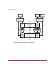
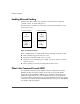
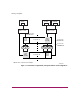
At any time, host port 1 is active on only one controller, and host port 2 is active
on only one controller. The other ports are in standby mode. In normal operation,
both host port 1 on controller A and host port 2 on controller B are active. A
representative configuration is shown in Figure 8. The active and standby ports
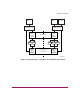
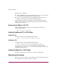
share port identity, enabling the standby port to take over for the active one. If one
controller fails, its companion controller (known as the surviving controller) takes
control by making both its host ports active, as shown in Figure 9.
Units are divided between the host ports:
■ Units 0–99 are on host port 1 of both controllers (but accessible only through
the active port).
■ Units 100–199 are on host port 2 of both controllers (but accessible only
through the active port).
Transparent failover only compensates for a controller failure, and not for failures
of either the Fibre Channel link or host Fibre Channel adapters.