getting started and general reference guide hp StorageWorks Core Switch 2/64 www.hp.
Notice Safety notices © Hewlett-Packard Company, 2002. All rights reserved. Any servicing, adjustment, maintenance, or repair must be performed only by authorized service-trained personnel. Part number: A6509-96001 Edition: E0502 Format conventions Hewlett-Packard Company makes no warranty of any kind with regard to this material, including, but not limited to, the implied warranties of merchantability and fitness for a particular purpose.
CONTENTS Revision History . . . . . . . . . . . . . . . . . . . . . . . . . . . . . . . . . . . . . . . . . . . vii Updates . . . . . . . . . . . . . . . . . . . . . . . . . . . . . . . . . . . . . . . . . . . . . . . . . . vii About This Guide . . . . . . . . . . . . . . . . . . . . . . . . . . . . . . . . . . . . . . . . . . vii Intended Audience . . . . . . . . . . . . . . . . . . . . . . . . . . . . . . . . . . . . . . . . . vii Related Publications . . . . . . . . . . . . . . . . . . . . . . . . . . .
Saving the System Configuration Files . . . . . . . . . . . . . . . . . . . . . . . . . Backing up the Switch Configuration Settings . . . . . . . . . . . . . . . . . Restoring the System Configuration Settings . . . . . . . . . . . . . . . . . . Setting Up Speed Negotiation . . . . . . . . . . . . . . . . . . . . . . . . . . . . . . . . . 4 Operating the Switch . . . . . . . . . . . . . . . . . . . . . . . . . . . . 45 Turning the Switch On and Off . . . . . . . . . . . . . . . . . . . . . . . . . . . .
General . . . . . . . . . . . . . . . . . . . . . . . . . . . . . . . . . . . . . . . . . . . . . . . . . . 16-Port Card Specifications . . . . . . . . . . . . . . . . . . . . . . . . . . . . . . . . . . Port Specifications . . . . . . . . . . . . . . . . . . . . . . . . . . . . . . . . . . . . . . . Control Processor Card Specifications . . . . . . . . . . . . . . . . . . . . . . . . . . Memory Specifications . . . . . . . . . . . . . . . . . . . . . . . . . . . . . . . . . . . Battery Specifications . . .
vi getting started and general reference guide
Revision History May 2002 First release. Updates For the most current information about the HP StorageWorks Core Switch 2/64, visit the support Web site located at http://www.hp.com/support/coreswitch264. For information about product availability, configuration, and connectivity, consult your HP account representative. About This Guide This guide provides the following information about the switch: Chapter 1 Overview Overview information about the switch.
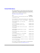
Related Publications The following publications contain related product information. The hp StorageWorks Core Switch 2/64 Documentation CD provided with the switch contains all of the publications listed in the following table. These publications are also available for downloading at http://www.hp.com/support/coreswitch264.
1 OVERVIEW The HP StorageWorks Core Switch 2/64 is a high-performance core switch for large storage area networks, available with 32 to 128 ports (a 128 port switch is configured as two 64 port switches in a single chassis).
devices connected to the port. They are compatible with short wave-length and long wave-length SFP (small form factor pluggable) transceivers, universal and self-configuring, and capable of individually becoming FL_Ports (fabric loop ports), F_Ports (fabric ports), or E_Ports (expansion ports). The HP StorageWorks Core Switch 2/64 is 14 rack units in height, has an air-cooled chassis, and can be installed in either an HP Rosebowl II or Compaq/Rittal rack.
1 2 3 4 Slot # 5 6 Power Supply #4 7 8 9 10 Exhaust Vent Power Supply #3 CP Card Power Supply #2 16-Port Card Power Supply #1 AC Power Switch Grounding Strap Connector AC Power AC Power Connector Connector (Provide Power to PS #1 & 3) AC Power Switch (Provide Power to PS #2 & 4) Figure 1.
The Blower Assembly Side of the Chassis Figure 2 shows the blower assembly side of the HP StorageWorks Core Switch 2/64 chassis, which provides access to the following components: • WWN card and bezel - Provide LEDs for monitoring the switch and storing WWN and IP address information. • Blower assemblies - Three blower assemblies on the back of the chassis, individually hot-swappable. For operating information for the components, refer to Chapter 4, “Operating the Switch” on page 45.
Port Card and CP Card LEDs 1 o o WWN Bezel 2 o o 3 o o 4 o o 5 o o 6 o o 7 o o 8 o o 9 o o Power Supply LEDs 10 o o pwr4 o pwr3 o pwr2 o pwr1 o Blower Power LED Blower Fault LED Blower Handle Blower Assembly #1 Blower Assembly #2 Blower Assembly #3 Figure 2.
Monitoring and Managing the Switch The HP StorageWorks Core Switch 2/64 can be managed in-band using Fibre Channel protocol or out-of-band by connecting to the Ethernet port. The management functions allow the administrator to monitor fabric topology, port status, physical status, and other information to aid in system debugging and performance analysis. Note The switch automatically performs Power-On Self Test diagnostics (POST) each time it is turned on and any errors are recorded in the error log.
In addition, the HP StorageWorks Core Switch 2/64 supports the following software: Supported Software Refer to Advanced Zoning hp StorageWorks advanced zoning user’s guide Fabric Watch hp StorageWorks fabric watch user’s guide Advanced Performance Monitoring hp StorageWorks advanced performance monitoring user’s guide Extended Fabrics hp StorageWorks distributed fabric user’s guide Remote Switch hp StorageWorks distributed fabric user’s guide ISL Trunking hp StorageWorks isl trunking user’s gui
8 getting started and general reference guide
2 INSTALLING THE SWITCH Installation Considerations and Safety Guidelines WARNING A fully populated HP StorageWorks Core Switch 2/64 weighs approximately 250 pounds and requires a minimum of two people and mechanical lift to install it. Before installing, verify that the additional weight of the chassis does not exceed the cabinet’s weight limits or unbalance the cabinet, including when some of the cards or power supplies are partially extended out of the chassis.
• If installing in a cabinet: – Verify that the additional weight of the chassis does not exceed the cabinet’s weight limits. – Ensure that all equipment installed in the cabinet is grounded through a reliable branch circuit connection. Do not rely on a secondary connection to a branch circuit, such as a power strip.
Note Order SFP transceivers separately from your HP StorageWorks Core Switch 2/64. The HP StorageWorks Core Switch 2/64 supports both SWL and LWL transceivers. Rear Mounting Brackets (B) HP StorageWorks Core Switch 2/64 (A) Rail Assemblies (C) Figure 3. Major Items Contained in the Shipping Carton(s) Table 1.
Table 1.
Hardware Identification Table 2 contains drawings and descriptions of the hardware used when installing the HP StorageWorks Core Switch 2/64 in an HP Rosebowl II or Compaq/Rittal rack. Use this table to help identify the hardware specified in the installation procedure in this chapter. Depending on the rack you use, you may not be using all of the hardware listed below. Note Table 2. Hardware Key #10-32 x .63” Phillips pan-head screws with integrated lock washers (4) 1/4-20 x .
WARNING Mount the switch as low as possible in the rack to ensure that the weight of the switch does not make the rack unstable. Fifteen Rack Units (RUs) are required to accommodate the switch and cable management. Rear of Rack Front of Rack Blower Assembly Side of the Switch Figure 4. Switch Mounted Back-to-Front and Low in the Rack WARNING The switch weighs approximately 250 pounds when fully loaded and requires a mechanical lift to move it safely.
To unpack and install the switch in a rack: 1. Remove the crate top of the shipping carton from pallet. Removing the crate top may require two people. 2. Check contents of the shipping carton to verify all the required parts and hardware are available. 3. Using a 1/2-inch socket wrench, remove the four bolts from the brackets that secure the switch to the pallet (see Figure 5). Because you will not need to use the bolts for this installation, you can discard them. Pallet Bolts (4x) Figure 5.
4. Remove the following items from the chassis: Note Complete the following steps before attempting to slide the switch onto the rack. The switch may not be installed from the front of the rack if you do not first remove the front door, door hinges, and front mounting brackets. Removal of the door hinges and front mounting brackets (steps 4b and 4c) is not required if the switch can be installed from the rear of the rack. Removal of the door (step 4a) is always recommended. a.
b. Remove the two door hinges by removing the eight #8-32 flat-head screws that hold the hinges to the chassis (see Figure 7). Note the top and bottom orientation of the hinges and save the screws to reattach the hinges later. #8-32 Flat-Head Screws (8x) Door Hinges (2x) Figure 7.
c. Remove the two front mounting brackets by removing the ten #10-32 flat-head screws on the left bracket and the seven #10-32 flat-head screws on the right bracket (see Figure 8). Note the difference between the left and right front mounting brackets and save the screws to reattach the brackets later. #10-32 Flat-Head Screws (17x) Front Mounting Brackets (2x) Figure 8.
5. The two rear mounting bracket sets consist of a rear-mount bracket and a flange. Attach the two rear-mount brackets to the chassis by completing the following steps: a. Separate the flanges from rear-mount brackets by removing the four #10-32 pan-head screws, two screws per set (see Figure 9). Save the screws to reinstall the flanges later. Rear-Mount Bracket (1x set) #10-32 Pan-Head Screws (2x) Flange (1x set) Figure 9.
b. Attach the left and right rear-mount brackets to the chassis by installing four #10-32 x 1/4” flat-head screws per bracket into the four top corner holes towards the blower assembly side of the switch as shown in Figure 10. Note that each bracket is marked with an “up” arrow. Rear-Mount Brackets (2x) #10-32 Flat-Head Screws (8x) Figure 10. Attaching the Brackets to the Chassis 6. Attach the left and right rail assemblies to the rack by completing the following steps: a.
e. Install each rail assembly to the inside of the rack columns with six screws per rail assembly, two on the front of the rack and four on the rear of the rack (see Figure 11). For an HP Rosebowl II rack, use 1/4-20 x .5” Phillips pan-head screws. For a Compaq/Rittal rack, use 1/4-20 x .5” Phillips pan-head screws with a .375” square mounting hole between the screw and the rack column. 1/4-20 Phillips Pan-Head Screws (6x set) Front of Rack 1/4-20 Phillips Pan-Head Screws (6x set) Adjusting Screws .
7. From the front side of the rack, attach each flange to the rack with four screws, two per flange. Install the bottom flange screw 30 holes above the top rail assembly screw and then install the top flange screw two holes above the bottom flange screw (see Figure 12). For an HP Rosebowl II rack, use 1/4-20 x .5” Phillips pan-head screws with integrated lock washers. For a Compaq/Rittal rack, use 1/4-20 x .5” Phillips pan-head screws with integrated lock washers with a .
8. On the left and right rear rack columns, install a Tinnerman nut two holes above the top screw of the rail assembly and another nut 34 holes above the top screw (see Figure 13). For an HP Rosebowl II rack, use M5 U-type Tinnerman nuts. For a Compaq/Rittal rack, use #10-32 Tinnerman nuts.
9. Slide the switch from the pallet onto the lift and then position the lift at the front of the rack. Note that the port side of the switch will go in first and will face out of the rear of the rack. The blower side will face out of the front of the rack (see Figure 14). Due to the weight of the switch, moving the switch requires two or three people. Front of Rack Rear of Rack Blower Assembly Side of the Switch Figure 14. Placing the Switch on the Lift 10.
11. From the rear side of the rack, reattach the following items to the chassis: a. Using the seven #10-32 flat-head screws removed earlier, reattach the right front mounting bracket to the chassis (see Figure 15). #10-32 Flat-Head Screws (17x) Front Mounting Brackets (2x) Rear of Rack Figure 15. Reattaching the Left and Right Front Mounting Bracket b. Using the ten #10-32 flat-head screws removed earlier, reattach the left front mounting bracket to the chassis (see Figure 15).
c. Using the eight #8-32 flat-head screws removed earlier, reattach the two door hinges (see Figure 16). #8-32 Flat-Head Screws (8x) Door Hinges (2x) Rear of Rack Figure 16. Reattaching the Door Hinges 12.Slide the switch into place so that the rack is flush against the flange.
13.From the front side of the rack, reattach the flanges to the rear-mount brackets with the four #10-32 pan-head screws you removed earlier from the rear mounting bracket sets (see Figure 17). Do not tighten the screws. Rear Mounting Bracket Set (Flange and Rear-Mount Bracket) Front of Rack #10-32 Pan-Head Screws (2x set) Figure 17.
14.From the rear side of the rack, install screws into the second and bottom positions on the right front mounting bracket through the Tinnerman nuts installed earlier (see Figure 18). For an HP Rosebowl II rack, use M5 Torx head screws with captive lock washers. For a Compaq/Rittal rack, use #10-32 x .63” Phillips pan-head screws with integrated lock washers. Do not tighten the screws.
16.Press the spring-loaded pins and reattach the door to the chassis. To ensure that the switch does not emit RFI, the switch door must be installed and kept closed during normal operation. CAUTION Do not connect the switch to the network until the IP address is correctly set. For instructions on how to set the IP address, see “Configuring the Switch” on page 32.
30 getting started and general reference guide
3 STARTING AND CONFIGURING THE SWITCH Providing Initial Power to the Switch 1. Connect the AC power cord retainer to the chassis: Adjusting Screw Chassis Screw Figure 19. Power Cord Retainer a. Orient one of the retainers as shown in Figure 19. b. Position the retainer tabs under the two screws on either side of a power connector on the chassis. Tighten both screws. c. Loosen the adjusting screw to allow the power cord to fit into the retainer. d. Repeat Step 1 for the other retainer. 2.
3. Tighten the adjusting screws on both retainers until the power cords cannot be disconnected. 4. Connect the power cords to a power source with voltage of 200 to 240 VAC, 50-60 Hz. HP recommends the use of two separate PDUs and two separate power sources to maintain high reliability. Each PDU must have at least one C19 connector. Do not mount the PDUs to the left of the switch door. This will inhibit door operation. Note 5. Flip both green AC power switches to “1”.
stored in the WWN card and in the flash memory of the CP cards, and is automatically mirrored to the standby CP card. Configuration information can be backed up by uploading the configuration to a workstation using the ConfigUpload command and can be downloaded to the active CP card using the ConfigDownload command. For information about commands and whether they can be entered through the active or standby CP card, refer to the hp StorageWorks fabric os reference.
Items Required The following items are required to configure and connect the HP StorageWorks Core Switch 2/64: • HP StorageWorks Core Switch 2/64 powered on, but not yet connected to a network or fabric. • Workstation computer with a terminal emulator application (such as HyperTerminal). • Serial cable provided with the switch. • Ethernet cable. • SFPs and FC cables as required to connect the switch to the fabric.
Configuration Procedure This procedure provides instructions for configuring and connecting the HP StorageWorks Core Switch 2/64 for use in a network and fabric. To configure and connect the switch: 1. Verify that the HP StorageWorks Core Switch 2/64 is on and POST is complete by verifying that all the power LED indicators on the 16-port cards and CP cards are displaying a steady green light. For more information about the LEDs, see “Interpreting LED Activity” on page 54. 2.
– For most UNIX systems, enter the following string at the prompt: tip /dev/ttyb -9600 e. When the terminal emulator application stops reporting information, press Enter to get the following login prompt: CP0 Console Login: f. Enter the administrative login information. The default administrative login is admin and the default password is password. At the initial login, the user is prompted to enter new Admin and User passwords.
Note Configuration changes can only be made through a session with the active CP card, although you can assign IP addresses to either CP card from a session with the active CP card. a. If the CP card in slot 5 is not the active CP card, disconnect the serial cable from the CP card, connect it to the CP card in slot 6, and log in as admin. b. Enter the ipAddrSet command at the prompt. Enter “2” for the CP card in slot 5 and “3” for the active CP card in slot 6. For example: ipAddrSet 2 c.
b. Enter the requested information for this IP address at the prompts: Ethernet IP Address [10.77.77.77]: Ethernet Subnetmask [0.0.0.0]: Fibre Channel IP Address [none]: Fibre Channel Subnet Mask [none]: The logical IP address is automatically updated immediately. c. To configure the IP address for logical switch 1, enter the following command at the prompt: ipAddrSet 1 d. Enter the requested information for this IP address at the prompts as described in Step 5b. e.
Note The logical switches and CP cards can now be accessed remotely, using telnet or Web Tools. Ensure that the switch is not being modified from any other connections during the remaining steps. The switch supports up to two telnet sessions with administrative privileges at the same time for each Ethernet port. 9. Optional: Customize the switch names for the logical switches if needed by completing the following steps.
c. Enter “Y” after the “Fabric parameters” prompt. Fabric parameters (yes, y, no, n): [no] y d. Enter a unique domain ID. Domain: (1..239) [1] 3 e. Complete the remaining prompts or press CTRL+D to accept the other settings and exit. f. Re-enable the switch by entering the following command: switchEnable 11. Optional: Specify any custom status policies by completing the following steps: a. To access the status policy, enter the following command at the prompt: switchStatusPolicySet b.
b. Position a cable so that the key (the ridge on one side of the cable connector) is aligned with the slot in the SFP, and then insert the cable into the SFP until the latching mechanism clicks. Note Cables are keyed so that they can only be inserted with the correct orientation. If a cable does not slide in easily, ensure it is correctly oriented. c. Repeat Steps 12a-b for the remaining ports. d. Organize the cables as required. 13.
Note To ensure a current configuration is available for uploading to a replacement switch, a routine backup of the configuration is recommended. Use the cfgSave and cfgEnable commands to save any zone configurations before the switch is powered off. The saved configuration is automatically reloaded by the switch on power up. If a configuration was enabled at the time it was saved, the same configuration is reinstalled with an automatic cfgEnable command.
location and filename of the configuration file, and password is the password for the user ID specified. If only configUpload is entered the system prompts you for each parameter. Example: switch:admin> configupload Server Name or IP Address [host]: 123.45.678.901 User Name [user]: kelev File Name [config.txt]: switch1 Protocol (RSHD or FTP) [rshd]: ftp Password: upload complete Restoring the System Configuration Settings To restore the system configuration settings from a backup: 1.
Setting Up Speed Negotiation There are two methods for configuring the ports on the HP StorageWorks Core Switch 2/64. The port can be set to auto-sensing mode, which allows the port to automatically be configured to the highest speed. Ports can also be set to a fixed speed of either 1 or 2 Gbps. To display the configuration settings of the ports on a switch, use the portCfgShow. The port speed is displayed as 1G (fixed speed of 1 Gbps), 2G (fixed speed of 2 Gbps), or AN (auto-negotiate).
4 OPERATING THE SWITCH Turning the Switch On and Off To provide power to the switch for the first time, refer to “Providing Initial Power to the Switch” on page 31. To turn on the switch: • Verify both power cords are connected to the AC power connectors on the port side of the chassis, and flip both green AC power switches to “1”. The green AC power switches illuminate when on. To turn off the switch: • Flip both AC power switches to “O”.
Allow the HP StorageWorks Core Switch 2/64 to run for a minimum of 10 minutes after powering on before powering off again. CAUTION Operating Information for System Components The HP StorageWorks Core Switch 2/64 can contain up to two logical switches, each with its own configuration: one for any 16-port cards in slots 1-4 and one for any 16-port cards in slots 7-10.
The switch can continue to operate while a 16-port card is replaced, but any devices connected to the 16-port card must be disconnected. To determine the status of a 16-port card: 1. Check the LED indicators on the 16-port card. Refer to Table 5 on page 56 for LED interpretation. 2. Check 16-port card status using the slotShow command. For additional information about this command, refer to the hp StorageWorks fabric os reference.
• Ethernet port The Ethernet port has an RJ-45 connector and is capable of speeds of 10/100 Mbps. A separate modem can be connected to each modem serial port, and then connected to the same or separate telephone lines for redundancy. Note The HP StorageWorks Core Switch 2/64 only detects modems during power on or reboot. If a modem is connected to an operating switch, the switch must be rebooted in order to detect the modem. The switch can continue to operate while a CP card is replaced.
#3 (color-coded blue), and the right power connector provides power to the power supplies in slots #2 and #4 (color-coded yellow). The HP StorageWorks Core Switch 2/64 can continue operating while a power supply is replaced if at least one power supply continues operating for every four 16-port cards installed. HP recommends a minimum of two power supplies. For a list of power supply specifications, see “Power Specifications” on page 71. To determine the status of a power supply: 1.
Unplugging a single power cable can power down the entire switch, depending on which power supply slots contain power supplies. CAUTION Two power cords are provided to connect the switch chassis to the PDUs. PDU and country specific cables are ordered separately. The AC power switches light up green when on. Blower Assemblies The switch is cooled by three blower assemblies located on the blower assembly side of the chassis.
2. Check blower assembly status using the fanShow command. The status for each blower assembly displays OK, absent, or faulty. If any of the blower assemblies are absent or faulty, contact HP support to order replacement parts, as necessary. For additional information about the fanShow command, refer to the hp StorageWorks fabric os reference. WWN Card and Bezel The WWN card and bezel are located at the top of the blower assembly side of the chassis.
SFPs The HP StorageWorks Core Switch 2/64 accommodates 32 to 128 SFPs. The SFPs supported are the SWL (short wavelength) and LWL (long wavelength) fibre-optics. Shortwave SFPs have black dots visible from the front. Longwave SFPs have blue dots visible from the front. The SFPs qualified by HP are 1Gb/2Gb capable. To install an SFP, position the SFP so that the key (the tab near the cable-end of the SFP) is on top and insert the SFP into the port until it is firmly seated and the latching mechanism clicks.
Table 4.
Interpreting LED Activity System activity and status can be determined through the activity of the LED indicators on the switch.
Direction to Push Yellow Ejector Button Power LED ! Status LED Port Speed LED (16x) Fibre Channel Port (16x) Port Status LED (16x) Ejector (2x) Direction to Push Yellow Ejector Button Figure 20.
Table 5. 16-Port Card LED Patterns Location of LED Purpose of LED Top LED Power Second LED Status Color of LED Status of Hardware Recommended Action No light (LED is off) 16-port card does not have incoming power. Ensure card is firmly seated and has power. Steady green 16-port card has incoming power. No action required. No light (LED is off) 16-port card is either healthy or does not have power. Verify Power LED is lit.
Table 5. 16-Port Card LED Patterns Location of LED Purpose of LED Left of each port, lower LED Port Status and Activity Color of LED Status of Hardware Recommended Action No light (LED is off) Either the 16-port card does Verify that Power LED is not have incoming power or lit, and check transceiver there is no light or signal and cable. carrier detected. Steady green Port is online (connected to No action required. an external device) but has no traffic.
LEDs on the Control Processor Card The CP card has four LEDs: a CP Card Power LED, a CP Card Status LED, a Link Status and Activity LED, and a Link Speed LED. The LEDs patterns may temporarily change during POST and other diagnostic tests.
Power LED Direction to Push Yellow Ejector Button Status LED RS-232 Modem Port 10101 Terminal Serial Port Link Status LED Ethernet Port Link Speed LED 10/100 Mb/s Ejector (2x) Direction to Push Yellow Ejector Button Figure 21.
Table 6. Control Processor Card LED Patterns Location of LED Purpose of LED Top LED Power Second LED Status Color of LED Status of Hardware Recommended Action No light (LED is off) CP card does not have incoming power. Ensure CP card is firmly seated and has power. Steady green CP card has incoming power. No action required. No light (LED is off) CP card is either healthy or Verify that Power LED is does not have incoming lit. power.
LEDs on the Power Supply Each power supply has three LEDs: the top LED is the Power Supply Power LED, the center LED is the Power Supply Predictive Failure LED, and the lower LED is the Power Supply Fail LED. If only one AC power switch is turned on, the Fail LED on each of the two power supplies without power will light up. The LEDs patterns may temporarily change during POST and other diagnostic tests. Note Locking Tab Handle Power LED ! Predictive Failure LED ! Fail LED Figure 22.
Table 7. Power Supply LED Patterns Location of LED Purpose of LED Upper LED Power Center LED Color of LED Status of Hardware No light (LED is off) Power supply does not have Ensure power supply is incoming power and is not firmly seated, switch has providing power to switch. incoming power, both power cables are connected, and AC power switches are on. Steady green Power has incoming power No action required. and is providing power to switch.
LEDs on the Blower Assemblies Each blower assembly has two LEDs: a Power LED and a Fault LED. The LEDs patterns may temporarily change during POST and other diagnostic tests. Note Fault LED Power LED Handle Thumbscrew (2x) Figure 23. Blower Assembly Table 8. Blower Assembly LED Patterns Location of LED Purpose of LED Left LED Power Operating the Switch Color of LED Status of Hardware Recommended Action No light (LED is off) Blower assembly does not have incoming power.
Table 8. Blower Assembly LED Patterns Location of LED Purpose of LED Right LED Fault Color of LED Status of Hardware Recommended Action No light (LED is off) Blower assembly is either healthy or does not have incoming power. Ensure blower assembly has incoming power. Steady orange Blower assembly has fully or partly failed. Replace blower assembly. Slow-flashing Blower assembly is not Pull unit out and reseat. If orange: seated correctly or is faulty.
CP Cards (Slots 5 and 6) 16-Port Cards (Slots 1-4 and 7-10) Power LED (Upper LED) Status LED (Lower LED) Power Supplies Power LED (Upper LED) Status LED (Lower LED) Power LED (Left LED) Status LED (Right LED) 1 o o 2 o o 3 o o 4 o o 5 o o 6 o o 7 o o 8 o o 9 o o 10 pwr4 o oo o pwr3 oo pwr2 oo pwr1 oo Figure 24. WWN Card and Bezel Interpreting POST Results Each time the switch is powered on or reset, the switch automatically performs POST, a system check during which LED patterns may vary.
Maintaining the Switch The HP StorageWorks Core Switch 2/64 does not require any regular physical maintenance and is designed to minimize the chance of failure, including field-replaceable units (FRUs) and diagnostic tests. For information on obtaining license keys or the most current technical support information about this product, visit the HP Web site at http://www.hp.com/support/coreswitch264.
Diagnostic tests may temporarily lock the transmit and receive speed of the links to a specific speed. Note Table 9. Diagnostic Test Commands and Descriptions Test Command Description Error Log errDump Displays the error log without page breaks. Switch Offline switchDisable Sets the switch to offline state necessary to run certain switch diagnostics. Memory Test ramTest Checks CPU RAM memory. Run offline or online.
Table 9. Diagnostic Test Commands and Descriptions 68 Test Command Description Cross Port Test crossPortTest Checks all switch paths. Frames transmitted by port M are looped back via external cable and received at port N. Run offline or online. Spin Silk Test spinSilk Checks all switch paths at the maximum speed of 1 Gbps. Frames transmitted by port M are looped back via external cables and when received by port N are sent again by port M in an external loop. Run offline.
5 SPECIFICATIONS Switch Components The HP StorageWorks Core Switch 2/64 consists of the following components: • A 14U chassis, designed to be mounted in a standard 19-inch rack. Two HP StorageWorks Core Switch 2/64 switches may be mounted in a standard 42U rack. • 16-port cards in configurations of 2 to 8 cards per chassis, with 16 optical ports per card, compatible with SFPs. • Two CP cards, each with: – One modem serial port with a DB-9 connector (full RS-232).
• A WWN card and bezel. • Three blower assemblies for forced-air cooling that flows from the blower assembly side of the chassis to the port side of the chassis. The fans provide adequate cooling for the maximum switch power rating of 102 Watts. • Two jumper cables that allow switch to PDU connections Physical Dimensions The following table lists the dimensions of the HP StorageWorks Core Switch 2/64. Table 10. Physical Specifications Dimension Value Height 14U (24.11 in./61.24 cm) Depth 27.9 in. (70.
Table 11. Component Weights Component Value CP Card 5.6 pounds (2.5 kg) 16-Port Card 8.6 pounds (3.9 kg) Card Filler Panel 3.2 pounds (1.6 kg) Cable Management Tray 0.6 pounds (0.27 kg) Facility Requirements To ensure correct operation of the switch, the facility where the switch is used must meet the following requirements: • Input Power Requirements: 200-240 VAC, 12A, 50-60 Hz. • Adequate supply circuit, line fusing, and wire size, as specified by the electrical rating on the chassis nameplate.
To remove power to the HP StorageWorks Core Switch 2/64, disconnect both power cables. WARNING The power supplies are universal and capable of functioning worldwide without using voltage jumpers or switches. They meet IEC 61000-4-5 surge voltage requirements and are autoranging in terms of accommodating input voltages and line frequencies. Each power supply has its own built-in fan for cooling, pushing the air towards the port side of the switch.
Environmental The following table lists the acceptable environmental ranges. The requirements for non-operating conditions are also provided for acceptable storage and transportation environments. Table 13.
General The following table lists the general specifications for the HP StorageWorks Core Switch 2/64. Table 14.
Table 14. General Specifications Specification Description Fabric initialization Complies with FC-SW 5.0 IP over Fibre Channel (FC-IP) Complies with FC-IP 2.
serial stream. The parallel data is expected to be “8B/10B” encoded data or equivalent. The ports are compatible with optical SWL (short wave-length: 780-850 nm), and optical LWL (long wave-length: 1270-1350 nm), SFPs, and SFP-compatible cables. The strength of the signal is determined by the type of SFP in use. The ports are universal and self-configuring, and are capable of becoming F_Ports (fabric ports), FL_Ports (fabric loop enabled), or E_Ports (expansion ports).
WARNING There is danger of explosion if the battery is incorrectly replaced. All used batteries must be discarded according to the manufacturer’s instructions. Contact HP support if the real time clock begins to lose time. Terminal Serial Port Specifications Each CP card provides a terminal serial port with a DB-9 connector with an RS-232 signal subset (see Figure 21 on page 59).
Modem Serial Port Specifications Each CP card has a modem serial port with a fully RS-232 compliant DB-9 connector (see Figure 21 on page 59). For dust and ESD protection, a cover is provided for the serial port and should be kept on the port whenever the serial port is not in use. Note The modem port can be used to attach a modem to each CP card and perform dial-in support operations including switch configuration and troubleshooting.
Post Specifications The HP StorageWorks Core Switch 2/64 performs POST by default each time the chassis is powered on (cold boot) or the switch is rebooted. The switch can be rebooted using the switchreboot, reboot, or fastboot commands. The fastboot command reboots the switches without running POST. A CP card failover event results in a reboot for the affected CP card. POST includes a number of diagnostic tests. Test results can be monitored through LED activity, the error log, or command-line interface.
80 getting started and general reference guide
PRODUCT REGULATORY INFORMATION FCC EMC Statement (USA) This equipment has been tested and found to comply with the limits for a Class A digital device, pursuant to Part 15 of the FCC Rules. These limits are designed to provide reasonable protection against harmful interference when the equipment is operated in a commercial environment.
Germany Noise Declaration Geräuschemission (Deutschland) Geräuschemission nach ISO 9296 (33° C): LpA m 62,4 dB (Beobachterposition) VCCI EMC Statement (Japan) Harmonics Conformance (Japan) BSMI EMC Statement (Taiwan) RRL EMC Statement (Korea) 82 getting started and general reference guide
Laser Safety A. Certification and Classification Information When equipped with native Fibre Channel adapters, this product contains a laser internal to the small form factor pluggable (SFP) transceiver modules. In the USA, the SFP module is certified as a Class 1 Laser product, conforming to the requirements contained in Department Of Health and Human Services (DHHS) regulation 21 CFR, Subchapter J. The certification is indicated by a label on the metal SFP housing.
Battery Disposal Statement The Lithium Ion battery used in this product may be harmful to the environment if not disposed of properly. Please follow the local, state or country regulations regarding the proper disposal of these batteries. Battery Disposal Statement Bij dit produkt zijn batterijen geleverd. Wanneer deze leeg zijn, moet u ze niet weggooien maar inleveren als KCA.
Declaration of Conformity Product Regulatory Information 85
86 getting started and general reference guide