
3.6.1 HP PolyServe Software for Windows File Serving Administration Guide (T5392-96019, July 2008)
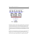
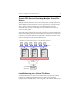
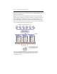
Table Of Contents
Chapter4:ConfigureVirtualCIFSServers 20
VFS1,VFS2,andVFS3.TheVirtualFileShareisconfiguredidenticallyon
eachVirtualCIFSServer.
Node1isprimaryforVirtualCIFSServerVFS1,node2isprimaryfor
VFS2,andnode3isprimaryforVFS3.Eachnodeisabackupfortheother
VirtualCIFSServers.CIFSclients
connecttotheloadbalancer(suchas
round‐robinDNSorahardwareload balancer)andtheclientsarethen
routedtooneofthenodes.Ifanodegoesdown,itsclientswillbefailed
overtoabackupnodeandaccesswillcontinue.
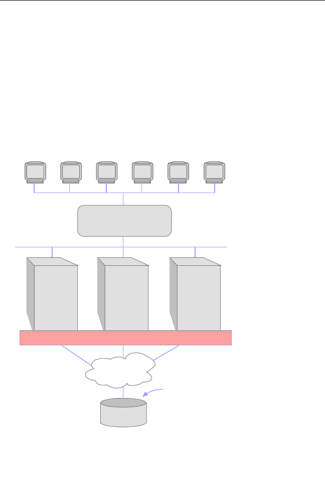
CIFS clients accessing Virtual File Share
s1
Ethernet
FC Fabric
For each Virtual CIFS Server,
Virtual File Share
s1
points to
the x:\s1 PSFS filesystem
Disk Array
All servers are providing Virtual File Share
s1
via Virtual CIFS Servers VFS1,
VFS2, and VFS3. DNS round robin or a hardware load balancer is configured
to route the CIFS clients to a Virtual CIFS Server on first connect or on a
reconnect after a failure.
DNS round robin or
hardware load balancer
Primary:
VFS2 with
Virtual File
Share
s1
Backup:
VFS1, VFS3
Primary:
VFS3 with
Virtual File
Share
s1
Backup:
VFS1, VFS2
Primary:
VFS1 with
Virtual File
Share
s1
Backup:
VFS2, VFS3
Matrix Server