
3.4.0 MxFS for CIFS Administration Guide

Chapter 3: Configure CIFS with Virtual CIFS Servers 19
Copyright © 1999-2006 PolyServe, Inc. All rights reserved.
VFS1, VFS2, and VFS3. The Virtual File Share is configured identically on
each Virtual CIFS Server.
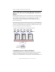
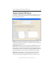
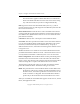
Node 1 is primary for Virtual CIFS Server VFS1, node 2 is primary for
VFS2, and node 3 is primary for VFS3. Each node is a backup for the other
Virtual CIFS Servers. CIFS clients connect to the load balancer (such as
round-robin DNS or a hardware load balancer) and the clients are then
routed to one of the nodes. If a node goes down, its clients will be failed
over to a backup node and access will continue.
CIFS clients accessing Virtual File Share
s1
Ethernet
FC Fabric
For each Virtual CIFS Server,
Virtual File Share
s1
points to
the x:\s1 PSFS filesystem
Disk Array
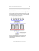
All servers are providing Virtual File Share
s1
via Virtual CIFS Servers VFS1,
VFS2, and VFS3. DNS round robin or a hardware load balancer is configured
to route the CIFS clients to a Virtual CIFS Server on first connect or on a
reconnect after a failure.
DNS round robin or
hardware load balancer
Primary:
VFS2 with
Virtual F ile
Share
s1
Backup:
VFS1, VFS3
Primary:
VFS3 with
Virtual F ile
Share
s1
Backup:
VFS1, VFS2
Primary:
VFS1 with
Virtual F ile
Share
s1
Backup:
VFS2, VFS3
Matrix Server