
HP Direct-Connect External SAS Storage for HP BladeSystem Solutions Depoyment Guide

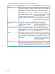


The following standards are maintained in the sample configurations:
Dual domainSingle domainDevice
Depending on the type of server blade
used, two or four switches are installed in
Depending on the type of server blade
used, one or two switches are installed in
SAS switches:
the c-Class enclosure, providing dual pathsthe c-Class enclosure, providing a single
between the server blades and the
switches.
nl
path between the server blades and the
switches.
nl
When using full-height or half-height server
blades, two switches are required, installed
When using full-height or half-height
server blades, one switch is required.
nl
in adjacent interconnect bays, for example,
in interconnect bays 5 and 6.
nl
When using double-density server blades
in the c7000 enclosure, two switches are
When using double-density server blades
in the c7000 enclosure, four switches are
required, installed in different interconnect
rows, for example, in interconnect bays
5 and 7. required, installed in different interconnect
rows, for example, in interconnect bays 5,
6, 7, and 8.
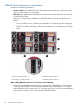
Two controllers are installed in
MSA2000sa controller enclosures,
One controller is installed in MSA2000sa
controller enclosures, providing a single
MSA2000sa SAS controller
modules:
providing an alternate path between the
switches and the MSA2000sa.
path between the switch and the
MSA2000sa.
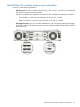
Four I/O modules are installed in the
MDS600 storage enclosure, providing
Two I/O modules are installed in the
MDS600 storage enclosure, providing a
MDS600 SAS I/O modules:
alternate paths between the switches andsingle path between the switch and the
the dual-port SAS drives in each MDS600
enclosure drawer.
single-port SATA drives in each MDS600
enclosure drawer.
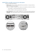
Two cables are connected between the
switch and the storage enclosure: one from
A single cable is connected between the
switch and the storage enclosure. If ports
Cabling:
the primary controller or I/O module andon the switch and the storage enclosure
one from the secondary controller or I/Oare available, connect an additional cable
module. If ports on the switch and thebetween the devices, for improved
performance. storage enclosure are available, connect
an additional cable between the devices,
for improved performance.
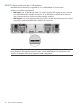
When creating and assigning zone groups to server bays, assign server bays 1–8 to
zone groups associated with storage connected to switch ports 1, 2, 3, or 4. Assign
Zoning:
server bays 9–16 to zone groups associated with storage connected to switch ports
5, 6, 7, or 8. For more information, see “Zoning requirements and device mappings”
(page 51).
84 Introduction