
HP StorageWorks 1500 Modular Smart Array maintenance and service guide (356606-002, October 2006)
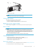

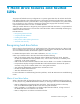
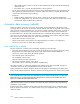

3. While pressing the power supply module latch (1) to the left, grasp the module handle and pull the
defective power supply out of the chassis (2).
1
2
15494
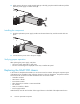
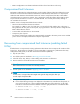
Installing the component
1. Slide the replacement power supply module into the MSA chassis bay until the module clicks into
place.
15495
2. Connect the AC power cord to the power supply.
Verifying proper operation
After replacing the power supply, verify that:
• The power supply Status LED is solid green.
• No new error messages are displayed on the array controller LCD panel.
Replacing the MSA1500 chassis
In the event of a backplane board failure, a new chassis must be ordered. All original component parts
of the MSA can be reinstalled in their respective locations on the new backplane. The parts that will be
remo
ved from the old chassis and then reinstalled in the new chassis include:
• Controllers or blank
• Hard drives or blanks
• Powe
r button module
• Fibre Channel I/O modules or interconnect blank
• Fan modules
• SCS
I I/O modules or blanks
• Power supply modules
When finished, write the serial number of the original chassis on the label of the replacement chassis.
92
Customer replaceable components