
HP StorageWorks 1500 Modular Smart Array maintenance and service guide (356606-002, October 2006)
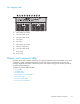
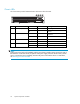
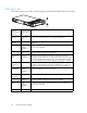

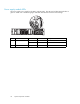

Slot diagram la
bel
1 3 4 5 6 7 8 9 10
1
PS 1PS 2
0
52
1
12
63
2
74
5
8
2
15523
1
Fibre Channel I/O module
2
SCSI I/O mod
ule (bus 3)
3
SCSI I/O module (bus 2)
4
Fan module
5
Fan module
6
Fibre Channel I/O module
7
SCSI I/O module (bus 1)
8
SCSI I/O mo
dule (bus 0)
9
Power supply
10
Power supply
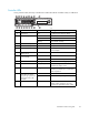
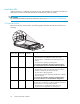
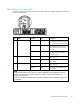
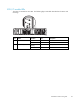
Chassis and component LEDs
The MSA chassis and its modular components are equipped with LEDs. When the fault LED on any MSA
component is amber, promptly determine the reason for the alert by examining the component, the
messages displayed on the MSA controller LCD panel, and system event logs (such as those provided by
HP Systems Insight Manager).
The following sections define the LEDs:
•ChassisLEDs
• Controller LEDs
•HarddriveLEDs
• Fibre Channel I/O Module LEDs
• Fan module LEDs
• SCSI I/O module LEDs
• Power supply module LEDs
maintenance and service guide
21