
Veritas Storage Foundation 5.0 Cluster File System Administration Guide Extracts for HP Serviceguard Storage Management Suite, Second Edition, May 2008


Cluster File System Architecture
About Veritas Cluster Volume Manager Functionality
Chapter 2
21
About Veritas Cluster Volume Manager Functionality
CVM supports up to 8 nodes in a cluster to simultaneously access and manage a set of
disks under VxVM control (VM disks). The same logical view of the disk configuration
and any changes are available on each node. When the cluster functionality is enabled,
all cluster nodes can share VxVM objects. Features provided by the base volume
manager, such as mirroring, fast mirror resync, and dirty region logging are also
supported in the cluster environment.
NOTE RAID-5 volumes are not supported on a shared disk group.
To implement cluster functionality, VxVM works together with the cmvx daemon
provided by HP. The cmdx daemon informs VxVM of changes in cluster membership.
Each node starts up independently and has its own copies of HP-UX, Serviceguard, and
CVM. When a node joins a cluster it gains access to shared disks. When a node leaves a
cluster, it no longer has access to shared disks. A node joins a cluster when Serviceguard
is started on that node.
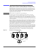
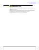
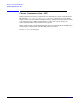
Figure 2-1 illustrates a simple cluster consisting of four nodes with similar or identical
hardware characteristics (CPUs, RAM and host adapters), and configured with identical
software (including the operating system). The nodes are fully connected by a private
network and they are also separately connected to shared external storage (either disk
arrays or JBODs) via Fibre Channel. Each node has two independent paths to these
disks, which are configured in one or more cluster-shareable disk groups.
The private network allows the nodes to share information about system resources and
about each other’s state. Using the private network, any node can recognize which nodes
are currently active, which are joining or leaving the cluster, and which have failed. The
private network requires at least two communication channels to provide redundancy
against one of the channels failing. If only one channel is used, its failure will be
indistinguishable from node failure—a condition known as network partitioning.
Figure 2-1 Example of a Four-Node Cluster
Redundant
Fibre Channel
Connectivity
Cluster-Shareable
Disks
Redundant Private Network
Node 0
Master
Node 1
Slave
Node 2
Slave
Node 3
Slave
Cluster-Shareable
Disk Groups