
Storage Multi-Pathing choices in HP-UX Serviceguard environments, August 2009


6
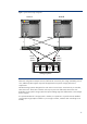
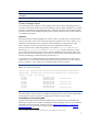
Figure 1: Typical Cluster Storage Configuration
h p Integrity rx7640
StandbyPower
Power
Remote
SPPresent
Run
Attention
Fault
hp StorageWorks MSA
HPStor ageWor ks
ModularSmar tAr r ay
1000
6 5 4 3 2 1 0
IML
1 0 /1 0 0
PWR
ER R
10 9 8 71 5 1 4 1 3 1 2 1 1
h pS to ra g e W o rks
E d g e S w itc h 2 /1 6
6 5 4 3 2 1 0
IML
1 0 /10 0
PW R
ER R
10 9 8 715 1 4 1 3 1 2 1 1
h pS to ra g e W o rk s
E d g e S w itch 2 /16
h p Integri ty rx7640
StandbyPower
Power
Remote
SPPresent
Run
Attention
Fault
Node-A
Node-B
HBA-1
HBA-2
HBA-3
HBA-4
Ctr-A
- port-1
- port-2
Storage System
FC-Switch-1 FC-Switch-2
Ctr-B
- port-1
- port-2
1
2
3
4
5 7
8
6
LUN
A
LUN
C
LUN
B
LUN
D
While this configuration example consists of sufficient FC connectivity from a high availability point of
view, additional paths might be required if the application has specific storage performance
requirements.
Individual storage systems distinguish from each other in several ways. Some have only 2 controllers,
others have more. Some have controllers with only one port to the SAN while others have more.
Depending on the specific storage system the optimal cabling might look different than in the example
shown in figure 1.
An important attribute of a storage system is whether I/O operations to a specific LUN are handled
concurrently through multiple controllers or just a single controller, while the other controller(s) act as
standby.