
Managing Serviceguard 11th Edition, Version A.11.16, Second Printing June 2004

Troubleshooting Your Cluster
Replacing Disks
Chapter 8 327
ILT cable is connected to an HBA, then termination must be disabled on
that HBA. Disabling the termination is done on the HBA by removing
the termination resistor packs, setting the appropriate DIP switches on
the HBA, or by programmatically disabling termination, depending on
the HBA being used. (Consult the documentation for the HBA to see
which method works for a particular HBA.)
ILT cables can be used in combination with Y-cables to allow additional
nodes to be connected to the shared SCSI bus. Some SCSI cables
available from HP have combined ILT and Y-cable functionality. Any
nodes connected to the middle connector of a Y-cable must also have
SCSI termination disabled on the HBA’s.
When an ILT cable is used, it is possible to physically disconnect a host
from the end of the shared SCSI bus without breaking the bus’s
termination, allowing the remaining nodes in the cluster to continue to
access the shared SCSI bus while the repairs are being made.
Similarly, it is possible to physically disconnect a host from the middle
connector of a Y-cable on a shared SCSI bus without breaking the bus’s
termination.
Whether using ILT cables or Y-cables, however, it is strongly
recommended that you do not try to physically reconnect an HBA to the
shared SCSI bus without first halting all nodes connected to that shared
SCSI bus. This is because it is very easy to inadvertently short out a pin
in the connector against the chassis ground, which would damage the
other HBA’s connected to the shared SCSI bus, and bring the entire SCSI
bus down.
NOTE You cannot use inline terminators with internal FW/SCSI buses on D
and K series systems, and you cannot use the inline terminator with
single-ended SCSI buses. You must not use an inline terminator to
connect a node to a Y cable.
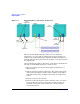
Figure 8-1 shows a three-node cluster with two F/W SCSI-2 buses. The
solid line and the dotted line represent different buses, both of which
have inline terminators attached to nodes 1 and 3. Y cables are also
shown attached to node 2.