
HP Serviceguard A.11.20- Managing Serviceguard Twentieth Edition, August 2011
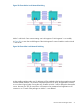
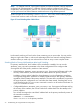


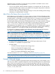

Figure 25 Cluster Before Local Network Switching
Node 1 and Node 2 are communicating over LAN segment 2. LAN segment 1 is a standby.
In Figure 26, we see what would happen if the LAN segment 2 network interface card on Node
1 were to fail.
Figure 26 Cluster After Local Network Switching
As the standby interface takes over, IP addresses will be switched to the hardware path associated
with the standby interface. The switch is transparent at the TCP/IP level. All applications continue
to run on their original nodes. During this time, IP traffic on Node 1 will be delayed as the transfer
occurs. However, the TCP/IP connections will continue to be maintained and applications will
continue to run. Control of the packages on Node 1 is not affected.
How the Network Manager Works 71