
Configuration Rules for a Mixed HP 9000 / Integrity Serviceguard Cluster, March 2007
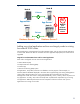
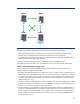
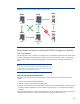
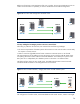
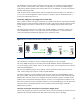


Table Of Contents
- Executive summary
- Version history
- Introduction
- Architectural rules and typical configurations
- Specific ISV information
- HP Superdome Hybrid Servers
- Typical configuration examples
- Transition to Integrity with HP Superdome hybrid servers and mixed clusters
- Adding one Integrity server to a two-node HP 9000 cluster
- Adding two HP Integrity servers to a two-node HP 9000 cluster
- Adding one critical application and two new Integrity nodes to existing four-node HP 9000 cluster
- Mixed clusters as transition aid from HP 9000 to Integrity in a multi-tier SAP environment
- HP 9000 to Integrity transition service utilizing HP Serviceguard cluster technology
- How to implement a mixed HP 9000 / Integrity HP Serviceguard cluster
- For more information
Th
st
e database and central instance of the BW system are split in two packages. The BW database
over.
ixed cluster in production, the resource requirements of the ERP
database system increase beyond the capabilities of node A. The positive experience gained with the
ing Integrity systems to the mixed
d redeployed as additional application server outside the cluster.
New five-node mixed HP 9000 / Integrity cluster
ays on node C, while the BW central instance is configured to run on the newly added Integrity
node (node E). Because the BW central instance does not run any database, it can fail over between
HP 9000 and Integrity nodes.
Node D remains as the common failover node for all applications that normally run on node A, B, C,
or E. Its own non-critical application will be shut down or limited in resource entitlements before a
mission-critical application fails
Second step: adding one more Integrity node to mixed cluster
After a couple of months running the m
first HP Integrity server make it a natural choice to continue add
cluster.
The following figure shows the new mixed cluster. The ERP database is moved from node A to the
newly added node F. Node A—now without a mission-critical application—is removed from the
cluster an
Figure 12.
Node C
The configuration of nodes B, C, and D, including their applications, are unchanged.
he newly added HP Integrity server (node F) hosts the ERP database. Because this database now
ilover
ERP
ance impact on the BW system.
s perform well and have plenty of resources left idle. On the other side, the
application layer of both the ERP and the BW system start showing resource shortages.
Node A
T
ru
ns on an Integrity system, node D, which is an HP 9000 system, can no longer function as a fa
node for the ERP database.
The previously added HP Integrity server (node E), which runs the BW central instance at normal
times, will be configured as a failover node for the ERP database.
The WLM configuration can be extended to node E to grant resources to the ERP database when it
fails over to node E. Alternatively, the BW central instance could be moved to node D before the
database fails over from node F to E to completely eliminate perform
Nodes E and F could perform bidirectional failover; however, to avoid performance problems on the
BW central instance server that could affect all BW users, HP recommends failing over the BW central
instance to the less utilized ERP application server (node D), rather than the highly active ERP
database server (node F).
Third step: converting the mixed cluster to a homogenous Integrity cluster
The new HP Integrity server
Old
ERP App2
PA
Node E
Node B
BW CI
Node D
Node F
PA
BW DB
PA
ERP CI
IPF IPF
PA
ERP App
ERP DB
25