
Configuration Rules for a Mixed HP 9000 / Integrity Serviceguard Cluster, March 2007
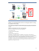
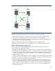
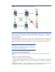
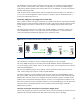
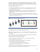


Table Of Contents
- Executive summary
- Version history
- Introduction
- Architectural rules and typical configurations
- Specific ISV information
- HP Superdome Hybrid Servers
- Typical configuration examples
- Transition to Integrity with HP Superdome hybrid servers and mixed clusters
- Adding one Integrity server to a two-node HP 9000 cluster
- Adding two HP Integrity servers to a two-node HP 9000 cluster
- Adding one critical application and two new Integrity nodes to existing four-node HP 9000 cluster
- Mixed clusters as transition aid from HP 9000 to Integrity in a multi-tier SAP environment
- HP 9000 to Integrity transition service utilizing HP Serviceguard cluster technology
- How to implement a mixed HP 9000 / Integrity HP Serviceguard cluster
- For more information
Before one of the three critical applications fails over to node D, the non-critical application server on
node D will be shut down or optionally, its resource entitlements will be reduced using WLM.
Figure 10. Initial four-node homogeneous HP 9000 cluster
First step: adding the first Integrity node to convert to a mixed cluster
After being in production for some time, the customer faces the following challenges:
• The resource requirements of the BW systems did increase to a level at which node C cannot satisfy
the requests in a timely manner.
• Node C cannot be upgraded because further investment in HP 9000 servers is not allowed.
The requirements are met by adding one new HP Integrity servers to the four-node HP 9000 cluster
and splitting off the BW central instance from the BW database. This enables the CI portion of the
BW system to run independently of its database portion on the same or on different nodes.
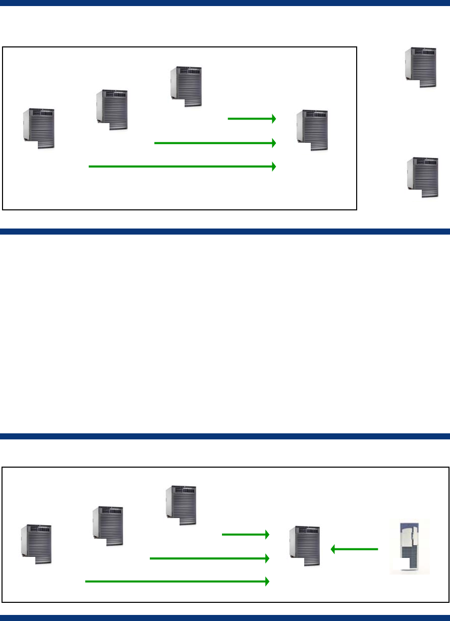
The following figure shows the new mixed cluster. The additional application servers that reside
outside the cluster still remain in the configuration but are not shown.
Figure 11. New five-node HP 9000 / Integrity SAP cluster with ERP and BW system
The configuration of node A and B, with the ERP database and central instance, remains unchanged.
Node E
BW CI
IPF
Node A
ERP DB
PA
Node B
ERP CI
PA
Node C
BW DB
PA
App
PA
Node D
App Server
PA
App Server
PA
Node A
ERP DB
PA
Node B
ERP CI
PA
Node C
PA
Node D
BW DB/CI
PA
App Server
24