
Configuration Rules for a Mixed HP 9000 / Integrity Serviceguard Cluster, March 2007
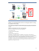
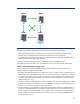
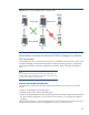
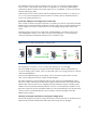
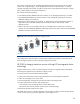


Table Of Contents
- Executive summary
- Version history
- Introduction
- Architectural rules and typical configurations
- Specific ISV information
- HP Superdome Hybrid Servers
- Typical configuration examples
- Transition to Integrity with HP Superdome hybrid servers and mixed clusters
- Adding one Integrity server to a two-node HP 9000 cluster
- Adding two HP Integrity servers to a two-node HP 9000 cluster
- Adding one critical application and two new Integrity nodes to existing four-node HP 9000 cluster
- Mixed clusters as transition aid from HP 9000 to Integrity in a multi-tier SAP environment
- HP 9000 to Integrity transition service utilizing HP Serviceguard cluster technology
- How to implement a mixed HP 9000 / Integrity HP Serviceguard cluster
- For more information
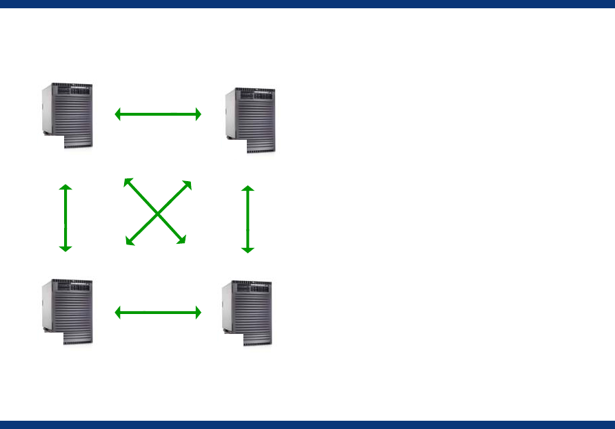
Figure 8. Existing four-node HP 9000 cluster
Node
HR
PA
Node
ERP
PA
Node
NFS
PA
Node
PA
Financials
(FI)
After being in production for some time, the customer faces the following challenges:
• The current HP 9000 cluster is missing its service level agreements (SLA) during failover times
because all four nodes became fully utilized over time by their primary applications.
• One additional mission-critical application—a Customer Relationship Management (CRM) system—
must be introduced and made highly available.
• Further investment in HP 9000 servers is prohibited in favor of HP Integrity servers.
The challenges are met by adding two new HP Integrity servers to the four-node HP 9000 cluster.
New six-node mixed HP 9000 / Integrity cluster
Two new HP Integrity servers are added to the four-node homogeneous HP 9000 cluster. The
following high-level changes are performed:
• The highly available NFS application is moved from node C to node E—the first HP Integrity server
added to the cluster. This addition frees node C to provide all resources to a HR, ERP, FI, or NFS in
case either of the nodes A, B, D, or E fail. Alternatively, a non-critical application could be placed
on node C, which will be either shut down or limited in resource entitlements in case of a primary
node failure (A, B, D, or E).
• The newly introduced CRM application is placed on node F—the second HP Integrity server added
to the cluster. Because this application consists of a database which doesn’t allow heterogeneous
fail-over, it cannot fail over to node C, an HP 9000 system.
• The first HP Integrity server (node E) is configured to be the failover node for the CRM application.
Initially, it is expected that node E is powerful enough to meet the resource requirements, even in a
failover scenario when CRM and NFS run on it together. If the combined resource requirements of
NFS and CRM later increase above the level at which node E can successfully handle them, NFS
can be pushed to node C.
22