Choosing the Right Disk Technology in a High Availability Environment A Technical Whitepaper Bob Sauers bobs@cup.hp.com General Systems Division General Systems Solution Lab Advanced Technology Center URL http://gsslweb.cup.hp.com/ATC May 1996 © Copyright 1996, Hewlett-Packard Company Page 1 DRAFT -- Revision 2.
Table of Contents INTRODUCTION . . . . . . . . . . . . . . . . . . . . . . . . . . . . . . . . . . . . . . . . . . . . . . . . . . . . . 4 Disk Link Technology Comparisons . . . . . . . . . . . . . . . . . . . . . . . . . . . . . . . . . . . . . . . HP-FL disk links . . . . . . . . . . . . . . . . . . . . . . . . . . . . . . . . . . . . . . . . . . . . . . . . . SCSI disk links . . . . . . . . . . . . . . . . . . . . . . . . . . . . . . . . . . . . . . . . . . . . . . . . . . Fibre Channel . . . . . . . .
Disk Link Technology . . . . . . . . . . . . . . . . . . . . . . . . . . . . . . . . . . . . . . . . . . . . Number of Targets on a Disk Link . . . . . . . . . . . . . . . . . . . . . . . . . . . . . . . . . . Performance benchmarks . . . . . . . . . . . . . . . . . . . . . . . . . . . . . . . . . . . . . . . . Summary of performance of various disk technologies . . . . . . . . . . . . . . . . . . 38 38 40 40 HIGH AVAILABILITY (HA) DISK CONSIDERATIONS . . . . . . . . . . . . . . . . . . . . . . . .
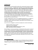
INTRODUCTION Disk technologies have been rapidly changing with new generation hardware available every nine to 12 months. Computer buyers have been having trouble keeping up with the changes let alone understanding them. RAID1 technology in particular has become popular in the marketplace. RAID is an acronym for Redundant Arrays of Inexpensive Disks and was designed as an alternative to Single Large Expensive Disks (SLED) used on supercomputers and mainframes.
This Whitepaper will attempt to remove some of the mystery associated with various disk technologies and will discuss the advantages and disadvantages of each, with the goal being an easy-to-use roadmap for choosing the right disk technology.
There are many terms associated with SCSI. Several versions of the protocol and several versions of the bus exist. SCSI-1, SCSI-2 and SCSI-3 refer to the protocol to which a particular device conforms. On the HP 9000 series 800, HP supports devices that conform to the SCSI-2 protocol only. SCSI-3 specifies an enhanced protocol that includes, for example, support for 32 LUNs (SCSI Logical Units) rather than the 8 supported in SCSI-2. SCSI has defined two speeds: Standard SCSI and Fast SCSI.
Channel-SCSI Multiplexer, enabling existing F/W SCSI disks to be located up to 2 kilometers from the host computers. The Fibre Channel-SCSI Multiplexer is henceforth called the FC/SCSI Mux for brevity. The FC/SCSI Mux can have two Fibre Channel (FC) ports and that capability is very important for High Availability, since it provides a redundant link to the disks if the primary link goes down. Alternatively, the second FC port can be used to connect to a different host in a High Availability Cluster.
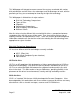
Table A: Disk Link Comparisons Link Link Bandwidth (MB/sec) Peak Fibre Channel Fibre ChannelSCSI Multiplexer * ** *** **** Maximum Devices per Link 2+ kilometers **** N/A 2 kilometers per Fibre Channel port (max 2 ports) 60 (15 per F/W SCSI link) Sustained 1 Gbit / sec 60 (5000 I/Os per second) Maximum Link Length 30-40 (2-3 K I/Os per second) Computer systems do NOT count as devices Computer systems DO count as devices Includes cabling internal to the disk drive Distance between nodes in the n
! ! Disk arrays using RAID technology Solid state disks Standalone disk drives with LVM mirroring Standalone disk drives are simple, non-array type disks; i.e., they do not use implement any RAID level in hardware. A new acronym has emerged to describe these simple disks: JBODs, which stands for "Just a Bunch Of Disks". JBODs can be single disk spindles with a controller and power supply or can be combined into towers or racks with a single power supply.
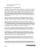
data corruption. The application can run on either of the SPUs, but only one at a time. When the primary system fails, access to the data shifts to the surviving SPU. Also with this configuration, the loss of one of the disk drives, the cable or even one of the host adapters in the SPU will not prevent access to the data since another copy resides on a separate disk link. MirrorDisk/UX automatically handles the access to multiple copies of the data in both normal and failure scenarios.
Since there are two internal SCSI busses each with its own connectors, power cords, power supplies, and fans, LVM mirroring can be accomplished using a single HASS without having any SPOFs. Each SCSI bus must be connected to a different F/W SCSI host adapter when mirroring in a single HASS to maintain HA and remove the host adapter as an SPOF. As with older JBODs, each storage module in a HASS consumes one SCSI target address.
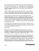
Primary Mirror Primary Mirror HASS Chassis # 1 HASS Chassis # 2 Figure 2: Typical High Availability Configuration with the High Availability Storage System (HASS) LVM Mirror Consistency LVM has two mechanisms for maintaining consistency between the mirrors. The default mechanism is to use the Mirror Write Cache (MWC). The MWC is kept in memory and is periodically written to the disk as a Mirror Consistency Record (MCR) in case of OS failure.
capacity disk drives, this results in a limit of 40 GB per F/W SCSI card. The number of F/W SCSI cards in a system is constrained first by slots in the SPU and further by performance considerations. Since this paper is concentrating on High Availability solutions, the standalone disks must then be mirrored, cutting the maximum usable capacity by 50%. This issue will be discussed further in the section on Capacity.
can live with the scheduled aspect of the replacement, especially since the replacement will occur in much less time than if a T500 had to be shut down and rebooted. Global hot spare functionality can be simulated with JBODs if a spare spindle is available on each side of the mirror. With modification of one step, the procedure that allows quiescent or on-line replacement of a JBOD will instead allow a hot spare to be reassigned to take over for a failed mechanism.
(1) One controller may be designated as a master controller with the other controllers acting as slaves. This method was implemented in the HP-FL array models C2258HA and C2259HA and the Fast/Wide SCSI array models C2439JA/JZ and C2440JA/JZ. (2) The second method incorporates a higher level storage processor that controls the complete functions of the RAID array.
RAID level 0/1 sector interleaved groups of mirrored disks; this is sometimes called RAID level 1/0 or RAID level 10 Since there is no data protection with RAID level 0, the only benefit is the potential for increased performance due to the data being spread across multiple disks. HP has implemented a special case of RAID level 0 called Independent Mode, in which the interleaving group size is one, effectively resulting in each disk being treated as if it were a non-RAID disk.
chained together, each supports the connection to a computer system, thus supporting a total distance of 1 km end-to-end. The physical link peaks at 5 MB / sec. On-line replacement of failed disk mechanisms is available in RAID 3 mode only. Since RAID level 3 provides relatively poor performance on HP-UX systems, these arrays are most often used in mirrored configurations using LVM mirroring, with the array setup in Independent Mode (a special case of RAID 0).
HP-FL HP-FL HP-FL P-BUS P-BUS HP-FL P-BUS P-BUS Figure 3: Typical High Availability Configuration with HP-FL Disk Arrays (FLDAs) F/W SCSI Disk Arrays A disk array similar to the FLDA is available from HP with a F/W SCSI interface and has two configurations. These disk arrays will be henceforth called SCSI DA for brevity.
maximum of 6 F/W SCSI DAs are possible due to a 3-bit DIP switch for the SCSI address setting. The number is 6 rather than 8 since the two SPUs should have the highest priority SCSI addresses of 7 and 6. Like the FLDA, SCSI DAs can be used with HA software as discussed in the section on JBODs.
! ! ! ! ! multiple internal SCSI busses deskside and rackmount models redundant and hot-swappable: # power supply # fan module # dual storage processors optional on Models 10 & 20 dual storage processors (optional) on Models 10 & 20 for performance redundant storage processor(s) in case of failure Cost, capacity and the features listed above make the HADA the practical choice in many situations where several hundred Gigabytes of storage is required. HADAs can be configured in RAID 0, 1, 0/1 and 5.
failure of the primary path (host adapter, cable or storage processor), LVM will automatically switch to the redundant path. The PV Links feature is necessary to support the redundant storage processor available on both the Model 10 and Model 20. This feature causes LVM to switch to the hardware path of the redundant storage processor when the corresponding primary storage processor fails. Note that the disk arrays must be configured with LVM to make use of this automatic switching feature.
Model 20 Storage Processor A (Std) & Cache (Optional) Model 20 Storage Storage Processor Processor A (Std) B (Opt) & Cache & Cache (Optional) (Optional) Storage Processor B (Opt) & Cache (Optional) Figure 5: High Availability Disk Array (HADA) with two Storage Processors using PV Links Advantages and Disadvantages of High Availability Disk Arrays (HADAs) (Note: not all of these advantages and disadvantages apply to the FLDAs and SCSI DAs) + smaller overall footprint for a given amount of storage Page 2
+ lower cost for moderate to large configurations + easy on-line replacement of failed disk mechanisms in RAID 1, 0/1, and 5 + capability to immediately assign a hot standby spindle to take over for a failed spindle + highest storage connectivity since each array uses only 1 or 2 SCSI target addresses + flexibility of configuration # select among a choice of RAID levels 0, 0/1, 5 # multiple RAID levels in one array concurrently + potential for high performance in a small I/O size, read-intensive environment
! up to 12 disk modules of 2.
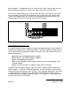
same LUN via both paths. The second path is for redundancy, in case of failure of the host adapter, cable or AutoRAID controller. PVLinks does permit concurrent access to different LUNs via both paths. To take advantage of this capability, multiple LUNs must be defined in the AutoRAID. The recommended number of AutoRAIDs per F/W SCSI interface changes depending upon the I/O load and upon the number of active AutoRAID controllers.
AutoRAID Controller A AutoRAID AutoRAID Controller Controller A B AutoRAID Controller B Figure 6: High Availability Configuration using the AutoRAID Disk Array and PVLinks Advantages and Disadvantages of AutoRAID Disk Arrays + smaller overall footprint for a given amount of storage + lower cost for moderate to large configurations + easy on-line replacement of failed disk mechanisms + hot standby is active and automatically assigned + highest storage connectivity since each array uses only 2 SCSI target
+ automatic AutoRAID controller failover with HP-UX Revision 10.
Multiple system connections are not made with multi-initiator busses. Rather, separate connections from each system is made to the Symmetrix using different SCSI ports on the Symmetrix. The Symmetrix can be configured with up to 128, 4 GB or 9 GB disk mechanisms assigned to up to 256 LUNs that can be configured on RAID 1 and RAID S groups. Internally, there are 32 SCSI busses (4 per disk director) with up to 4 disk mechanisms on each bus.
Primary Links Redundant Links Figure 7: Typical High Availability Configuration using the EMC Symmetrix ICDA and PVLinks Advantages and Disadvantages of Symmetrix ICDAs + + + + + + smaller overall footprint for a given amount of storage availability of 9 GB disk mechanisms most cost effective solution for very large configurations easy on-line replacement of failed disk mechanisms highest storage connectivity flexibility of configuration # administrator chooses the amount of space allocated to RAID 1 an
- overall performance depends entirely on workload and use of RAID 1 versus RAID S and SRDF - no boot support in a multi-initiator (shared bus) environment - high cost for small configurations - internal RAID group configuration and LUN assignment must be performed by EMC support personnel Solid State Disks Solid state disks are relatively new to the marketplace. The name is really an oxymoron. It is not a disk drive, but a disk drive replacement.
- not officially supported by HP-UX drivers CAPACITY Capacity is determined by the following factors: available interface slots in the SPU, operating system limitations, maximum number of disks per link, largest capacity disk drive available, performance guidelines, and testing. Tables B through F can be used to compare maximum capacities for the various disk types. The numbers in these tables are maximums. Actual configuration limits will be smaller in multi-initiator (shared bus) configurations.
Table B: Maximum Link Capacity by Disk Type Maximum targets Recommended & Link Limit Maximum Capacity per Target† Maximum Total Capacity per F/W SCSI Interface NOTES: † maximum capacity per target does NOT account for mirroring or data parity * standalone JBODs should be mirrored on different F/W SCSI busses ** configured with dual Storage Processors for maximum redundancy; each storage processor is attached to a different F/W SCSI bus *** 40 GB divided equally across two Storage Processors that are
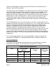
Table C: Maximum Supported Disks & Host Adapters by SPU Family Series Maximum HP-FL disks E G H I K T 0 16 32 32 32 160 Table D: Maximum Disk Capacity using F/W SCSI Standalone Disks SPU Model Using Standalone Disks Using Mirrored Standalone Disks T5XX 2,400 GB 1,200 GB K4XX 596 GB 298 GB K2XX 236 GB 118 GB K100 236 GB 118 GB Ixx 300 GB 150 GB Hxx 240 GB 120 GB Gxx 120 GB 60 GB Exx 120 GB 60 GB Table E: Maximum Disk Capacity using F/W SCSI Disk Arrays SPU Model Page
Table E: Maximum Disk Capacity using F/W SCSI Disk Arrays SPU Model Exx Using Disk Arrays in RAID Level 5 Using Disk Arrays in RAID Level 0/1 1,920 GB 1,190 GB Table F shows the maximum disk capacity supported on the various HP disk arrays at each supported RAID level.
! ! ! whether a mechanism has failed in a RAID 3 or 5 configuration disk link (HP-FL, SCSI, F/W SCSI) the number of targets on a disk link LVM versus non-LVM managed disks Organizations now usually employ Logical Volume Manager (LVM) to configure disks. All new high availability products including MC/ServiceGuard and MC/LockManager require the disks to be configured with LVM since these HA products use LVM to enforce exclusive or shared mode activation, and to perform disk locking.
Data Protection Mirroring can also be done in software or in hardware. Mirroring in software is accomplished via LVM, and uses more CPU cycles than does hardware mirroring. LVM mirroring appears to provide better read performance than does hardware mirroring using RAID level 0/1. This is due to LVM queuing the read onto the disk drive that has the shortest queue. Read performance has been seen to improve by as much as 40% with LVM mirroring.
sizes, although the performance is much lower than with standalone mirrored disks. RAID 3 performs best for I/Os of 64 KB or larger. The performance of a disk array configured in RAID 5 is very inconsistent. Small I/Os are most efficient for read operations since in the random case, multiple small I/Os can be processed concurrently by the disk array when they reference data on different disk mechanisms.
missing data that resides on the failed mechanism. This situation will severely degrade the overall performance of the disk array. Disk Link Technology The various disk link technologies have different peak and sustained bandwidths. Obviously, a faster bandwidth link will provide better performance. Currently, F/W SCSI offers the highest bandwidth and therefore the best performance.
The Performance Load Factor is normalized to a modern JBOD, which can sustain a 3.7 MB/sec transfer rate. For example, a HADA disk array Storage Processor can sustain an 8 MB/sec transfer rate, so it counts as two devices. Table G summarizes the Performance Load Factors associated with each device type.
10.0 for 5 HADA disk arrays each with two Storage Processors each, where each Storage Processor is attached to a different F/W SCSI bus OR 10.0 for 10 JBODs ! A two-node HA cluster with both host adapters active on the F/W SCSI bus 3.0 for the two host adapters AND 8.0 for 4 HADA disk arrays each with one Storage Processor each OR 8.0 for 4 HADA disk arrays each with two Storage Processors each, where each Storage Processor is attached to a different F/W SCSI bus OR 8.
Table H: Optimum I/O Environment (Best) I/O Size Small (1-2 KB) Large (>= 64 KB) Random Read-intensive Random Write-intensive Sequential Read-intensive Sequential Write-intensive ! ! RAID 0 ** ! Standalone / ! Standalone/ Mirrored (LVM)* ! RAID 3 * ! RAID 0 ** ! RAID 0/1 ! RAID 5 ! Standalone / Mirrored (LVM) ! RAID 0 ** ! ! RAID 0 ** RAID 3 Standalone / Mirrored (LVM) ! Standalone / Striped (LVM)** ! RAID 0 ** ! RAID 5 ! Standalone / Mirrored (LVM) ! RAID 0 ** ! RAID 0/1 Striped (LVM)** !
Table J: Solutions to Disk Single Points of Failure SPOF JBODs or HASS with LVM Mirroring RAID Disk Arrays Disk mechanism ! Mirror to different disk mechanism ! Use RAID level 1, 0/1, 3 or 5 in HADA, FLDA or SCSI DA Disk Power Supply ! ! Power Source ! Mirror to disk in different tray or tower; HASS has 2 power cords in one chassis No Solution except for AutoRAID which has 2 power cords in one chassis Disk Cooling System ! Mirror to different disk mechanism ! Use HADA, AutoRAID or Symmetrix
! ! ! ! ! performance backup strategy total capacity requirements power source redundancy total distance The need for on-line failed disk replacement versus scheduling downtime Can up to one hour of downtime be scheduled to replace a failed disk? If yes, then on-line failed disk replacement is not a requirement. Of course, replacement depends on the availability of a spare disk mechanism and the knowledge of how to do the replacement.
2-way LVM mirroring of standalone disks RAID level 0/1 or 1 RAID levels 3 or 5 Data redundancy is lost with the failure of any one disk mechanism with onelevel redundancy. Exposure time is the length of time it takes to replace the failed mechanism and recovery the data onto the replacement disk.
Purchase cost Purchase cost is usually a factor in determining how much availability can be provided. Cost is affected by: the number of cabinets required the number of I/O expansion modules (T500) required the number of SCSI cards required whether one- or two-level data redundancy is required An example cost comparison among various standalone disks and disk arrays follows the next section on footprint in Table K. Footprint The footprint is the amount of floor space required by the system.
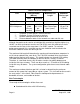
Table K: Cost & Footprint Comparison for 64 GB of Protected Disk Space Config A Config B Config C Config D Config E Method of Data protection LVM Mirroring RAID 5 RAID 1 RAID 5 LVM Mirroring Quantity of Arrays or Trays 16 2 4 8 16 Quantity of 2 GB disk mechanisms 64 40 64 40 64 Rack space in EIA Units (each) 4 9 9 7 7 Power consumption in Amperes (each) 1.2 4 4 3 3 # of F/W SCSI cards required 8 2 2 3 6 # of Cabinets required 2 1 2 2 4 1.08 0.54 1.08 1.
Table K: Cost & Footprint Comparison for 64 GB of Protected Disk Space Config A Notes: Config A: Config B: Config C: Config D: Config E: Config B Config C Config D Config E C3553RZ 2 GB JBODs in 8 GB tray configuration mirrored for 128 GB total disk space (64 GB protected) A3232A HADA arrays in RAID 5 mode for 80 GB total disk space (64 GB protected) configured with 2 Storage Processors and 32 MB cache; 20 mechanisms per array A3232A HADA arrays in RAID 1 mode for 128 GB total disk space (64 GB prote
Table L: Detail of Configurations Compared in Table K Configuration Qty Product # Price each Total Price C RAID 1 HADA Arrays 4 4 4 4 2 2 A3232A #320 #421 #532 28696A A1897A 15,000 26,265 2,000 10,160 1,295 2,450 D RAID 5 SCSI DAs 8 3 2 C2440JZ 28696A A1897A 23,000 1,295 2,450 184,000 3,885 4,900 192,785 E Independent Mode SCSI DAs 16 16 6 4 C2439JZ C2431A 28696A A1897A 18,000 4,300 1,295 2,450 288,000 68,800 7,770 9,800 374,370 213,700 2,590 4,900 221,190 Performance Performance of the
on-line backup. Consistency refers to the ability of the backup to provide a selfcontained copy of all of the data. Some Relational Database systems provide an on-line consistent backup facility either as a tool, or as a procedure using OS backup tools. Off-line backups can be performed by first shutting down the application and then doing the backup. During the time that the backup occurs, access to the data is not allowed.
Power source redundancy To ensure the highest level of availability, data should be protected by multiple power sources. This is possible today only with standalone mirrored disks. The loss of one power source or circuit will not prevent access to the data. Of course, this only makes sense if used together with MC/ServiceGuard where the systems that can run the application are powered separately, also.
Table M: Disk Selection Matrix by Technology Technology Criterion data redundancy ! 3-way full protection ! 2-way full protection If Required, then choose from this list of options ! ! If Not a Requirement, then choose from this list LVM mirrored LVM mirrored or RAID 0/1 ! RAID 3 or 5 N/A lowest cost RAID 5 HADA or AutoRAID LVM mirrored smallest footprint RAID 5 HADA or AutoRAID RAID 0/1 LVM mirrored No Single Points of Failure (SPOFs) LVM mirrored, HASS, AutoRAID, Symmetrix RAID 5 HADA (excep
C - HP-FL RAID disk arrays (FLDA) D - F/W SCSI RAID disk arrays (SCSI DA) E - High Availability disk arrays (HADA) F - Solid state disks G - High Availability Disk Array with AutoRAID NOTES: RAID levels are given as Rn, where n is the RAID level. Notes are referenced as *n, where n is the note number. Relative rankings are referenced at VH, H, M and L for very high high, medium and low.
Table N: Disk Selection Matrix by Product Availability Requirement A B C D E F G redundant cooling Yes *7 Yes Yes Yes Yes ??? Yes hot-replaceable cooling N/A Yes No No Yes ??? Yes redundant controller Yes *7 Yes *7 No No Yes ??? Yes hot-replaceable controller N/A N/A No No Yes ??? Yes redundant link cable Yes *7 Yes *7 Yes *8 Yes *9 Yes *10 Yes *9 Yes redundant SPU interface Yes *7 Yes *7 Yes *8 Yes *9 Yes *10 Yes *9 Yes concurrent offline backup Yes
NOTES: *1 requires possible removal from rack, opening of the tower or tray, and a many-step complex procedure *2 requires a multi-step complex procedure; mechanisms can be easily removed and replaced from the front *3 requires quiescence of the application, several LVM commands, possible slide-out from the rack, opening of the tower or tray *4 requires quiescence of the application; mechanisms can be easily removed and replaced from the front *5 requires a procedure similar to that of on-line or q
Page 55 DRAFT -- Revision 2.