
Best Practices for HP BladeSystem Deployments using HP Serviceguard Solutions for HP-UX 11i (May 2010)


9
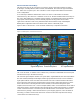
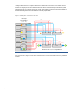
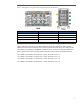
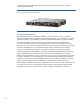
Figure 6: HP BladeSystem c7000 Enclosure Interconnect Bay Numbering
Server blade signal Interconnect number Interconnect bay label
NIC 1 and NIC 3 ( embedded ) 1 – Orange hexagon
NIC 2 and NIC 4 ( embedded ) 2 – Orange hexagon
Mezzanine 1 3, 4 – Yellow square
Mezzanine 2 5, 6 and then 7, 8 – Green circle/Blue diamond
Mezzanine 3 7, 8 and then 5, 6 – Blue diamond/Green circle
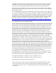
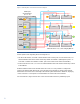
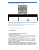
HP BladeSystem Onboard Administrator
BladeSystem Onboard Administrator (OA) (figure 7) is located below the interconnect bays and
provides component management in c-Class enclosures by:
• Detecting component insertion and removal
• Identifying components and required connectivity
• Managing power and cooling
• Controlling components
Administrators access the BladeSystem OA in several ways:
• Remotely through the web browser graphical user interface (GUI)
• Scriptable command line interface (CLI)
• On-site through the built-in Insight Display diagnostic LCD panel on the front of the enclosure
• OA with KVM (Keyboard, Video, Mouse) module allows direct connection to the enclosure with a
keyboard, video monitor, mouse or KVM switch through a VGA port
When a component is inserted into a bay, the BladeSystem Onboard Administrator immediately
recognizes and identifies the component through presence signals on each bay. If a component is
removed from a bay, the BladeSystem Onboard Administrator deletes the information about that
component from its current configuration.
Each Onboard Administrator module has one Ethernet and one serial port that can be used to link
enclosures in a rack. Enclosure links are designed to support only c-Class enclosures in the same rack,
and both c3000 and c7000 enclosures can be linked and managed together. It is a best practice