
Best Practices for HP BladeSystem Deployments using HP Serviceguard Solutions for HP-UX 11i (May 2010)


8
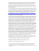
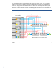
Figure 5: HP BladeSystem c7000 Enclosure Interconnect Diagram
Several points to note regarding the c7000 diagram are:
• The two LOM modules, each with a dedicated PCIe bus and two ports on each blade server, are
divided between interconnect switch module bays SWM-1and SWM-2 (although NIC ports 1 on
each LOM controller share SWM1 and NIC ports 2 share interconnect switch module SW2)
• Ports on Mezzanine cards 1, 2 and 3 are divided between interconnect switch module bays SWM-
3 thru SWM-8
With the additional interconnect module slots in the c7000, it is now possible to configure the
enclosure to eliminate both Mezzanine cards and interconnect modules as single points of failure
between the server blade and connectivity to the outside system infrastructure. Therefore, deploying
c7000 enclosures is a best practice recommendation for mission-critical environments.
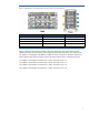
For visual reference, Figure 6 shows the c7000 enclosure Interconnect bay numbering layout.
Blade Slot # N = 2,4,6,8 for Integrity BL870c
Full-Height
Server Blade N
(N = 1…8)
PCIe x4
PCIe x8
PCIe x4
PCIe x8
PCIe x4
NIC
NIC
Mezz-1
Mezz-2
Mezz-3
4
3
2
1
4
3
2
1
4
3
2
1
2
1
2
1
GbX1
GbX2
SWM-7 SWM-8
SWM-1 SWM-2
SWM-3 SWM-4
SWM-5 SWM-6
2x
2x
N N+8 N N+8
N
N+8
N
N+8
N
N
N
N
N+8
N+8
N+8
N+8