
Best Practices for HP BladeSystem Deployments using HP Serviceguard Solutions for HP-UX 11i (May 2010)


7
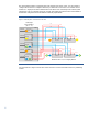
Figure 4: HP BladeSystem c-3000 Enclosure Rack and Tower Interconnect Bay Numbering
Server blade signal Interconnect bay Interconnect bay label
NIC 1, 2, 3, 4 (embedded) 1 – Orange hexagon
Mezzanine 1 2 – Yellow square
Mezzanine 2 3 and 4 – Green circle
Mezzanine 3 3 and 4 – Blue diamond
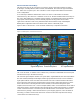
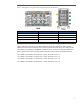
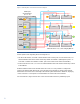
Figure 5 shows the interconnections between the server blades and interconnect switch module
(SWM) ports for the c7000 enclosure, with a similar physical interconnect bay color-coding scheme
(see figure 6). The mapping of the Bl860c and BL870c blade connections to the switch module bay
ports is similar to the c3000 enclosure; however since the enclosure has 8 available device bays,
• if a BL870c server blade is in device bays 1 and 2, the value of "N" is 2
• if a BL870c server blade is in device bays 3 and 4, the value of "N" is 4
• If a BL870c server blade is in device bays 5 and 6, the value of "N" is 6
• If a BL870c server blade is in device bays 7 and 8, the value of "N" is 8