
Best Practices for HP BladeSystem Deployments using HP Serviceguard Solutions for HP-UX 11i (May 2010)


5
To simplify the installation of the various Mezzanine cards and interconnect modules, the Onboard
Administrator, which manages the components within the enclosure, uses an “electronic keying”
process to detect any mismatch between the Mezzanine cards and the interconnect modules.
The power backplane provides 12V DC power to server blades, fans, and interconnects. Both the
signal midplane and separate power backplane in the c7000 enclosure have no active components,
thus improving reliability.
The AC input module providing power to the redundant power supply modules can be configured to
use a variety of different power delivery modes, depending on customer availability requirements and
cost constraints. The module can be configured to use either single-phase or three-phase AC for Non-
Redundant Power, Power Supply Redundant and AC Redundant power delivery modes. A detailed
description of these power modes and enclosure power configuration options is described in the
technology brief titled “Technologies in the HP BladeSystem c7000 Enclosure” available at
http://h20000.www2.hp.com/bc/docs/support/SupportManual/c00816246/c00816246.pdf. It
is recommended to use both Power Supply Redundant and AC Redundant power delivery modes to
achieve the highest levels of availability, if possible.
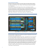
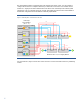
Figure 3 shows the interconnections between the device I/O from the server blades in the front of the
c3000 enclosure to the interconnect switch module (SWM) ports located at the rear of the enclosure
for data transfer. The color-coded symbols on the diagram are identical to the symbols used on the
physical enclosure and Onboard Administrator port mapping displays to identify the interconnect
bays (see figure 4). Each front device bay is connected through the signal backplane to each of the
rear interconnect bays. Interconnect bays 1 (for the c3000 / c7000) and 2 (for the c7000) are
dedicated to signals from the embedded NICs located on the server blade system board. The
remaining interconnect bays are available to accept signals from Mezzanine HBA cards mounted
directly on the server blades. The server blade Mezzanine card positions connect directly through the
signal mid-plane to the interconnect bays. The interconnect bays are designed to accept single-wide
or double-wide switch modules (SWMs) for interconnect bandwidth and form factor scalability.
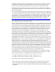
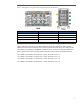
HP Integrity BL860c and BL870c blade servers are full-height and provide connections for two 2-port
embedded NICs, also known as “LAN on Motherboard”, or LOM, and up to three 4-port Mezzanine
HBAs (labeled Mezz-1 – Mezz-3) as shown in figures 3 and 4. PCIe (PCI Express) connectivity from
the blade system board to the LOM and Mezzanine HBAs uses paired groups of full-duplex
communication “lanes”. A single-wide lane provides a 1x 500MB/s transfer rate, and a double-wide
or two lanes provide a 2x transfer rate of1Gb/s. Mezzanine cards are categorized into “types” that
describe their data transfer capabilities. Type I Mezzanine cards provide 1x transfer rate, while Type
II Mezzanine cards provide 1Gb/s through a single lane. Embedded LOM and host bus adapters
installed in Mezzanine card slot 1 support single-wide lane interconnects, while Mezzanine slots 2
and 3 support either single-wide or double-wide lane interconnects. Figures 3 and 5 show the PCIe
lane connections available to the LOM and Mezzanine cards on the blade server.
The Integrity BL860c is a single-wide server blade. The designation “N” in the diagram is used to
map single-wide server blade connections to the switch module bay ports. The BL870c is a double-
wide server blade and follows a slightly different port mapping scheme in that:
• If a BL870c server blade is in device bays 1 and 2, the value of "N" is 2
• If a BL870c server blade is in device bays 3 and 4, the value of "N" is 4
Several points to note regarding the c3000 diagram are:
• All four LOM ports on each server blade use the same interconnect switch module bay SWM-1
• All four ports of Mezzanine card 1share the same interconnect switch module bay SWM-2
• Ports on Mezzanine cards 2 and 3 are divided between interconnect switch module bays SWM-3
and SWM-4