Best Practices for HP BladeSystem Deployments using HP Serviceguard Solutions for HP-UX 11i May 2010 Technical white paper Table of contents Executive Summary ......................................................................................................................... 2 BladeSystem Overview .................................................................................................................... 2 Hardware Components ....................................................................
Executive Summary HP continues to be tremendously successful in deploying server hardware consolidated into HP BladeSystem environments. The improved control of power consumption and workload management with HP Insight Dynamics – VSE software controlling the entire environment bring distinct advantages. HP Virtual Connect facilitates rapid deployment and infrastructure flexibility, reducing wiring and the effort to connect servers to network and SAN fabrics.
Figure 1: c-Class HP BladeSystem Enclosure Family HP BladeSystem c7000 enclosure HP BladeSystem c3000 Tower HP BladeSystem c3000 enclosure Both enclosures share common: • Half-height /full-height server blades • Interconnect modules • Mezzanine Host Bus Adapter (HBA) cards • Storage blades • Power Supplies (hot swappable and redundant) • Fans (hot-swappable and redundant) A comparison between the c3000 and c7000 enclosures is shown in Table 1.
Device and Interconnect Bays The interconnect bays for each enclosure can support a variety of Pass-Thru modules and switch technologies, including Ethernet, Fibre Channel, and InfiniBand. The enclosures support redundant I/O fabrics and can yield up to a 94% reduction in cables compared to traditional rack-mounted server configurations. One of the major differences between the c3000 and c7000 is in the number of available interconnect bays; the c3000 has 4 while the c7000 has 8.
To simplify the installation of the various Mezzanine cards and interconnect modules, the Onboard Administrator, which manages the components within the enclosure, uses an “electronic keying” process to detect any mismatch between the Mezzanine cards and the interconnect modules. The power backplane provides 12V DC power to server blades, fans, and interconnects. Both the signal midplane and separate power backplane in the c7000 enclosure have no active components, thus improving reliability.
Due to the limited number of available interconnect module slots in the c3000, it is not possible to configure the enclosure for complete redundancy to eliminate a Mezzanine card and interconnect module as a single point of failure between the server blade and connectivity to the outside system infrastructure. This is an important point to consider when deploying mission-critical environments an whether this configuration will meet defined availability requirements.
Figure 4: HP BladeSystem c-3000 Enclosure Rack and Tower Interconnect Bay Numbering Server blade signal Interconnect bay Interconnect bay label NIC 1, 2, 3, 4 (embedded) 1 – Orange hexagon Mezzanine 1 2 – Yellow square Mezzanine 2 3 and 4 – Green circle Mezzanine 3 3 and 4 – Blue diamond Figure 5 shows the interconnections between the server blades and interconnect switch module (SWM) ports for the c7000 enclosure, with a similar physical interconnect bay color-coding scheme (see figure 6).
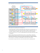
Figure 5: HP BladeSystem c7000 Enclosure Interconnect Diagram 2x Full-Height Server Blade N (N = 1…8) N 2x NIC N SWM-1 GbX1 PCIe x4 N+8 N+8 SWM-2 2 1 N 4 PCIe x4 Mezz-1 N 3 N+8 N+8 2 SWM-3 1 SWM-4 4 PCIe x8 Mezz-2 3 N 2 N+8 N N+8 1 SWM-5 PCIe x4 NIC 2 1 SWM-6 N+8 N+8 N N 4 PCIe x8 Mezz-3 3 SWM-7 SWM-8 2 1 GbX2 Blade Slot # N = 2,4,6,8 for Integrity BL870c Several points to note regarding the c7000 diagram are: • The two LOM modules, each with a dedicated PCIe b
Figure 6: HP BladeSystem c7000 Enclosure Interconnect Bay Numbering Server blade signal Interconnect number Interconnect bay label NIC 1 and NIC 3 ( embedded ) 1 – Orange hexagon NIC 2 and NIC 4 ( embedded ) 2 – Orange hexagon Mezzanine 1 3, 4 – Yellow square Mezzanine 2 5, 6 and then 7, 8 – Green circle/Blue diamond Mezzanine 3 7, 8 and then 5, 6 – Blue diamond/Green circle HP BladeSystem Onboard Administrator BladeSystem Onboard Administrator (OA) (figure 7) is located below the interco
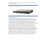
recommendation to verify that both Onboard Administrator modules have the same and latest firmware revisions installed. Figure 7: HP BladeSystem Onboard Administrator HP Integrity Blade Servers HP Integrity blade servers - the BL870c and BL860c - enable customers to run and consolidate business and mission-critical applications in the flexible BladeSystem c-Class infrastructure, providing superior virtualization, high availability, scalability, simplified management, and energy efficiency.
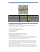
Table 2: HP Integrity Blade Comparison BL860c BL870c Processor Intel® Itanium® 9100 Processors 2 Sockets 1.66 GHz/18MB FSB667 1.42GHz/12MB FSB533 1.6GHz/12MB FSB533, single-core Note: 9000 series processor (Montecito) also supported Intel® Itanium® 9100 Processors 4 Sockets 1.6 GHz/24MB FSB533 1.6 GHz/18MB FSB533 1.
perspective, the next section of this white paper will describe how to incorporate Serviceguard into the solution to maximize overall availability.
configuration information from the active module. It remains as the standby until either a system administrator manually promotes it to the active module or the active module fails.
Figure 8: Example of Stacked Virtual Connect Ethernet Modules Fiber Channel SAN Connectivity 2-port Fiber Channel Mezzanine cards are available for connecting server blades to a SAN infrastructure. HP recommends using two FC Mezzanine cards for redundancy to eliminate the Mezzanine cards as a SPOF. When using Virtual Connect Fiber Channel modules, HP recommends deploying the modules as side-by-side interconnect bay pairs for module redundancy with each Fiber Channel port.
An improvement of this configuration would be to ensure the primary and standby LANs pass through different VC modules, with the output ports on the VC modules connected to separate Ethernet switches that are bridged together. This configuration would protect against the failure of a LOM port controller, the network ports on the Mezzanine card, a VC module, a switch or cabling, and would eliminate many more possible failure points.
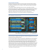
Figure 10: Onboard Administrator Window showing Device Bay 7 Port Mapping From the Port Mapping view, the embedded network ports, FC HBA ports from Mezzanine Slot 1 and Ethernet ports from Mezzanine Slot 2 are shown mapped to their respective interconnect bay ports. Note in this example configuration, ports 3 and 4 of the Quad-Port Mezzanine HBA are not mapped because there are no interconnect modules in enclosure interconnect bays 7 and 8.
Figure 11: Server Profile for BL860c installed in Device Bay 7 Primary site LAN and private heartbeat LAN assigned to Interconnect Bays 1 & 2 Standby site LAN and private heartbeat LAN assigned to Interconnect Bays 5 & 6 Fiber Channel Ports 1 and 2 assigned to Interconnect Bays 3 & 4 In summary, this example uses the following Virtual Connect server profile configuration to minimize SPOFs with the components that were available to this BL860c server blade: • LAN on Motherboard (LOM): – Port1: Site LAN –
Disaster Recovery solutions (i.e., Extended Distance Serviceguard clusters, Metrocluster, Continentalclusters) are fully supported with the HP BladeSystem BL860c (A and B versions) and BL870c Integrity server blades using the following HP-UX operating systems and Serviceguard versions: • HP-UX 11i v2 September 2006 (or later) with Serviceguard A.11.17 and SGeRAC A.11.17 (or later) • HP-UX 11i v3 September 2007 (or later) with Serviceguard A.11.18 and SGeRAC A.11.
– HP BLc 4Gb Fibre Channel Pass-thru Module (P/N 403626-B21) – Brocade 4/12 SAN Switch (P/N AE370A - Note P/N AE373A to upgrade the AE370 12 port switch to 24 ports is also supported) – Brocade 4/24 SAN Switch for c-Class BladeSystem (P/N AE372A) – Cisco MDS 9124e 12-port Fabric Switch (P/N AG641A) – Cisco MDS 9124e 24-port Fabric Switch (P/N AG642A) – HP B-series 8/12c SAN Switch (P/N AJ820A) – HP B-series 8/24c SAN Switch (P/N AJ821A or AJ822A) – HP BLc 4Gb Virtual Connect Fibre Channel Module (P/N 409513
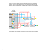
In this example, a 4-node Serviceguard cluster is configured in a single c7000 enclosure, with an EVA disk array used for shared storage between the cluster nodes. An HP Systems Insight Manager Central Management Server is also shown, which provides overall management of the systems environment from outside of the Serviceguard cluster. While this example shows 4 integrity server blades used as cluster nodes, it is also possible to use HP Integrity Virtual Machines as Serviceguard nodes.
Figure 13: Cluster Example Spanning Multiple c7000 Enclosures HP Systems Insight Manager (SIM) Central Management Server (CMS) Quorum Service (HP-UX OS) LAN VC Stacking Link Serviceguard cluster SAN c7000 BladeSystem Enclosure c7000 BladeSystem Enclosure EVA Disk Array In this example, a single 8-node Serviceguard cluster spans two c7000 enclosures, with 4 nodes in each enclosure attached to shared storage provided by an EVA disk array.
Advantages: • Protects against a complete blade enclosure failure • Provides the flexibility of moving workloads to another enclosure for planned maintenance (e.g.
– For more information on setting this parameter, see the Serviceguard Network Manager Inbound Failure Detection white paper at: http://docs.hp.com/en/5568/serviceguard.network.manager.pdf – This issue also affects HP-UX APA (Auto-Port Aggregation) link aggregates and APA failover groups (LAN_MONITOR mode) – This hardware issue and a list of available solutions is documented in the HP Support Communication Customer Advisory at: http://h20000.www2.hp.com/bizsupport/TechSupport/Document.
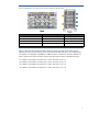
InfiniBand: • The HP BLc 4X DDR InfiniBand Mezzanine card, which requires the HP BLc 4X DDR IB Switch Module (figure 15), is supported with Serviceguard Figure 15: HP BLc 4X DDR InfiniBand Mezzanine card and HP BLc 4X DDR IB Switch Module • Considerations for InfiniBand use: – Few applications use native InfiniBand protocol; thus requiring the use of IPoverIB protocol (e.g.
Conclusion The HP BladeSystem has many redundant features within its design to make it highly available.
For More Information To read more, see: • HP BladeSystem: http://www.hp.com/go/bladesystem • HP Serviceguard Solutions: http://www.hp.com/go/serviceguardsolutions • HP Insight Dynamics: http://www.hp.com/go/insightdynamics • HP Insight Dynamics – VSE for Integrity servers: http://www.hp.com/go/vse Call to Action HP welcomes your input. Please give us comments about this white paper, or suggestions for LVM or related documentation, through our technical documentation feedback website: http://docs.hp.