
Understanding and Designing Serviceguard Disaster Recovery Architectures


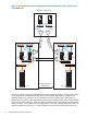
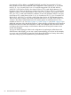


Refer to Figure 25 (page 64) for an example of an Extended Distance Cluster configuration in two
data centers with a third location.
Figure 25 Extended Distance Cluster with Two Data Centers
Node A Node B
Heartbeat Networks
over FDDI
Fibre Links For
Software Mirroring
Data Replication
Maximum distance
50 kilometers
Node C Node D
Storage
Site 1 Site 2
Storage
Network Switch Network Switch
Network Switch Network Switch
FC Switch
FC Switch
FC Switch
FC Switch
Cluster Lock Cluster Lock
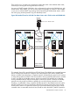
In the figure 26, Finisar (long haul) GBICs and cabling that supports up to 80 kilometers are used
for the ISL links between the Fibre Channel switches in the two data centers. The Inter switch links
between the Ethernet switches use GBICs and cabling that the switch vendor supports for up to
100 kilometers. The total distance supported between the two data centers are determined by the
shorter of the maximum distances supported for the ISLs by the Fibre Channel switch and Ethernet
switch vendors (not to exceed 100 kilometers). In this example, the distance between the data
centers is limited to 80 kilometers. The redundant network and Fibre Channel links between the
two data centers must be routed geographically differently, such that if the cables in one trench
are severed, the cables in the alternately routed trench will still provide both network and Fibre
Channel connectivity and allow the cluster to continue normally. This cluster is not allowed to
contain more than four nodes for Serviceguard clusters (due to the cluster lock limitation of four
nodes). For EC RAC clusters, the number of nodes allowed and the maximum distance supported
will vary, depending upon the HP UX revision and the volume manager being used (see Table 2
(page 51), Table 3 (page 51) and Table 4 (page 53) for details).
64 Extended Distance Cluster Configurations