
Understanding and Designing Serviceguard Disaster Recovery Architectures


• Serviceguard Disaster Recovery Products Compatibility and Feature Matrix (Metrocluster 3PAR
Remote Copy)
• Serviceguard Disaster Recovery Products Compatibility and Feature Matrix (Continentalclusters)
NOTE: If disks are not presented using NPIV, you must not present logical volumes (LVM) of the
physical host as disks to the guest. Instead, add the physical disks directly to the guests.
Virtual Partitions/Integrity VM on Separate Hosts
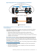
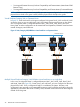
In Figure 21, each VM host has a VM guest configured. VM guests’ Host1_VM1 and Host2_VM2
access the array on one site while Host3_VM3, and Host4_VM4 access the array on the remote
site. Serviceguard cluster is configured between Host1_VM1, Host2_VM2, Host3_VM3 and
Host4_VM4. A similar configuration can be created with virtual partitions/VMWare virtual machines
instead of Integrity virtual machines.
Figure 21 vPar/Integrity VM/VMWare virtual machines on Separate Hosts
Array Replication
Serviceguard Cluster
Heartbeat Network
Host 1 Host 2 Host 3 Host 4
Host1_VM1 Host2_VM2
FC Switch FC Switch
Host3_VM3 Host4_VM4
Disk Arrays
Disk Arrays
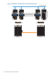
Multiple Virtual Partitions/Integrity VM/VMWare virtual machines on a single Host
In this case, Serviceguard cluster is configured between Host1_VM1, Host2_VM2, Host3_VM3
and Host4_VM4 (See Figure 22). Guests, host3_vm3 and host3_vm4, are configured on the same
physical host, host3. Such a configuration helps in consolidation of systems. However, such
configurations are generally not recommended because a single host failure might bring down the
applications in the entire data center. Similarly, vPars/VMWare virtual machines can be configured
instead of HP VM guests.
46 Metrocluster and Continentalclusters