Understanding and Designing Serviceguard Disaster Recovery Architectures HP Part Number: 719325-001 Published: March 2013
Legal Notices © Copyright 2013 Hewlett-Packard Development Company, L. P. Confidential computer software. Valid license from HP required for possession, use, or copying. Consistent with FAR 12.211 and 12.212, Commercial Computer Software, Computer Software Documentation, and Technical Data for Commercial Items are licensed to the U.S. Government under vendor’s standard commercial license. The information contained herein is subject to change without notice.
Contents 1 Disaster Recovery in a Serviceguard Cluster...................................................6 Evaluating the Need for Disaster Recovery...................................................................................6 What is a Disaster Recovery Architecture?...................................................................................6 Understanding Types of Disaster Recovery Clusters........................................................................
N-1 configuration..........................................................................................................31 N-1 Bidirectional configuration........................................................................................32 Continentalclusters With Cascading Failover.....................................................................32 Cascading Failover Using Metrocluster........................................................................33 Features of Continentalclusters .....
Common WDM Links for both TCP/IP Networking and Fibre Channel Data...............................60 Common SONET or SDH Links for both TCP/IP Networking and Fibre Channel Data..................61 Extended Distance Cluster with two Data Centers...................................................................62 Extended Distance Cluster configurations with Two Data Centers and a Third Location................63 4 Comparison of Disaster Recovery Solutions..................................................
1 Disaster Recovery in a Serviceguard Cluster Evaluating the Need for Disaster Recovery Disaster Recovery is the ability to restore applications and data within a reasonable period of time after a disaster. Most think of fire, flood, and earthquake as disasters, but a disaster can be any event that unexpectedly interrupts service or corrupts data in an entire data center: the backhoe that digs too deep and severs a network connection, or an act of sabotage.
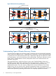
Figure 1 High Availability Architecture Node 1 fails Node 2 Node 1 pkg A disks pkg A mirrors pkg A pkg B pkg B disks pkg B mirrors Client Connections pkg A fails over to node 2 Node 2 Node 1 pkg A disks pkg A mirrors pkg B pkg B disks pkg A pkg B mirrors Client Connections This architecture, which is typically implemented on one site in a single data center, is sometimes called a local cluster. For some installations, the level of protection provided by a local cluster is insufficient.
Figure 2 Disaster Recovery Architecture Data Center A Fails pkg A Node 1 pkg B pkg C Node 3 Node 2 pkg D Node 4 Replication Link Data Center A Data Center B Client Connections packages A and B fail over to Data Center B Node 1 pkg C pkg D pkg A pkg B Node 3 Node 2 Node 4 Replication Link Data Center A Data Center B Client Connections Understanding Types of Disaster Recovery Clusters To protect against multiple points of failure, cluster components must be geographically dispersed: n
NOTE: “Metrocluster and Continentalclusters” (page 20), provides an overview of HP implementation of Metropolitan Cluster and Continental cluster while Chapter 3 provides an overview of Extended Distance Clusters. Disaster Recovery Architecture Guidelines Disaster recovery architectures represent a shift away from the massive central data centers and towards more distributed data processing facilities.
dictates) or store it offline in a vault. If a disaster occurs at one site, the offline copy of data is used to synchronize data at a remote site which functions in place of the failed site. Data is replicated using physical offline backup, therefore data consistency is fairly high, barring human error or an untested corrupt backup. However, data currency is compromised by the time delay in sending the tape backup to a remote site.
Figure 3 Physical Data Replication Physical Replication in Software Node 1 Node 2 Replication Physical Replication in Hardware (XP array) Node 1 Node 2 Replication MirrorDisk/UX is an example of physical replication performed in the software; a disk I/O is written to each array connected to the node, requiring the node to make multiple disk I/Os.
• For architectures using dedicated cables, the distance between the sites is limited by the cable interconnect technology. Different technologies support different distances and provide different “data through” performance. • For architectures using common carriers, the costs can vary dramatically, and the connection can be less reliable, depending on the Service Level Agreement.
Figure 4 Logical Data Replication Node 1 Node 2 LAN Logical Replication Advantages of using logical replication are: • The distance between nodes is limited only by the networking technology. • There is no additional hardware needed to perform logical replication, unless you want to boost CPU power and network bandwidth. • You can implement Logical replication to reduce risk of duplicating human error.
Using Alternative Power Sources In a high-availability environment, redundancy is applied to cluster components, such as PV links, redundant network cards, power supplies, and disks. In disaster recovery architectures another level of protection is required for these redundancies. The power supply for each data center that houses part of a disaster recovery cluster must be from a different circuit.
Figure 6 Reliability of the Network is Paramount Node 2 Node 1 Node 3 Node 4 Router Data Center A Data Center B Network uses single route Node 2 Node 1 Router Node 3 Node 4 Router Data Center A Data Center B Network uses redundant route Disaster Recovery Local Area Networking Ethernet networks is used to connect nodes in a disaster recovery architecture within the following guidelines: • Each node is connected to redundant hubs and bridges using two Ethernet host adapters.
Figure 7 Routing Highly Available Ethernet Connections in Opposite Directions Node 1 Node 3 hub From A to B bridge bridge hub Node 4 Node 2 hub bridge bridge Fr om Data Center A Data Center B C bridge hub to hub bridge A hub Node 5 Node 6 Data Center C Disaster Recovery Wide Area Networking Disaster recovery networking for continental clusters is directly tied to the data replication method.
more bandwidth you will need. The bandwidth provided by the following connection types vary: ◦ T1 and T3: low end ◦ ISDN and DSL: medium bandwidth ◦ ATM: high end • Reliability is affected regardless of whether data replication is performed, and therefore the consistency of the data is also affected when you need to fail over to the recovery cluster. Redundant leased lines should be used, and should be from two different common carriers, if possible.
Disaster Recovery Cluster Limitations disaster recovery clusters have limitations, some of which can be mitigated by good planning. Some examples of MPOF that may not be covered by disaster recovery configurations: • Failure of all networks among all data centers — This can be mitigated by using a different route for all network cables.
stress levels of the site administrator to restore the data center within a short time-frame can increase the possibility of a human error in the restoration process. ◦ Automated recovery procedures and processes can be transparent to the clients. Even if recovery is automated, you may choose to, or need to recover from some types of disasters with manual recovery.
2 Metrocluster and Continentalclusters Understanding Metrocluster Metropolitan Cluster A metropolitan cluster is a cluster that has alternate nodes located in two different parts of a city or in adjacent cities. Putting nodes further apart increases the likelihood that alternate nodes will be available for failover in the event of a disaster. A Metropolitan cluster requires a third location for arbitrator nodes or a quorum server.
Figure 9 Two Data Centers and Third Location with Arbitrators Highly Available Network pkg A pkg B Node 1 Node 2 Data Center B Data Center A Node 3 pkg C Node 4 pkg D Robust Data Replication Highly Available Network Arbitrator 1 Arbitrator 2 Arbitrators Third Location Terms and Concepts Arbitration When the cluster is part of a disaster recovery solution that has nodes located in more than one data center, loss of communication can easily occur unless redundant networking is implemented with
Arbitrator Nodes Arbitrator nodes is one of the arbitration mechanisms available in Serviceguard. A network split in a four-node cluster can result in two equal-sized partitions, but in a five-node cluster it cannot. The fifth node in the cluster, acts as the arbitrator by virtue of the fact that it makes the number of nodes in the cluster odd.
Figure 10 Two Data Centers and Third Location with Arbitrators or a Quorum Server replicated data for package A PVOL --------------------------------------- SVOL replicated data for package B PVOL --------------------------------------- SVOL replicated data for package C SVOL --------------------------------------- PVOL replicated data for package D SVOL --------------------------------------- PVOL Local XP Disk Array Remote XP Disk Array PV Links A pkg A Power Circuit 1 Network Switch Node 1 C1 Nod
In the Metrocluster environment, the same number of systems must be present in each of the two data centers (Data Center A and Data Center B) whose systems are connected to the disk arrays. However, when you use two arbitrator nodes in the third location, you can place one node in one datacenter and two nodes in another datacenter. Table 1 lists the allowable number of nodes at each main data center and the third location, up to a 16-node maximum cluster size.
For more information on configuring cross-subnet clusters, see the Managing Serviceguard manual available at http://www.hp.com/go/hpux-serviceguard-docs and Managing Serviceguard for Linux, available at http://www.hp.com/go/linux-serviceguard-docs. SADTA Metrocluster provides Site Aware Disaster Tolerant Architecture (SADTA) for complex workloads such as Oracle RAC database and SAP that use CFS, CVM, or SLVM.
The Volume Monitor must be configured as a service within a Metrocluster package. For Site Controller package, the volume monitor must be configured as part of workload packages that requires access to VxVM or LVM storage volumes. When a monitored volume fails or becomes inaccessible, the monitor service exits, causing the package to fail on the current node. The failover of package depends on its configured settings and on the application behavior.
(that is, if the hosts at the primary site fail but the disk remains up, the disk does not need to be resynchronized). • Metrocluster with Continuous Access for P9000 and XP is supported in a Three Data Center solution, providing the data consistency of synchronous replication and the capability of Continuous Access journaling replication to protect against local and wide-area disasters.
Figure 11 Sample Continentalclusters Configuration WAN ccmonpkg PRI_SCM_DB_PKG Recovery Group Packages REC_SCM_DB_PKG REC_CRM_DB_PKG Recovery Group Packages PRI_CRM_DB_PKG cconfpkg Continentalclusters Configuration Package cconfpkg Site A Node 1 Site A Node 2 Monitor Package ccmonpkg Site B Node 1 Site B Node 2 FC Switch FC Switch Monitor Package WAN WAN Converters Site A Disk Array Site A Cluster (Primary) Data Replication Links WAN Converters Site B Disk Array Site B Cluster (R
Recovery Group The packages that have the primary-recovery relationship is called a “Recovery Group“ in Continentalclusters. A “Recovery Group” can optionally have a rehearsal package, a data sender package or a data receiver package in addition to the mandatory primary and recovery packages. The rehearsal package is used for disaster recovery rehearsal operations.
Manual Recovery There are some cases where the cluster health cannot be determined because the monitoring happens over a network. For example, the cluster status can be reported as unreachable when either the network service has failed or when the cluster nodes are rebooting. Hence, information needs to be gathered from an independent source before proceeding with the recovery process. It is for this reason the recovery in Continentalclusters is manually initiated but automatically recovered.
Figure 12 Basic configuration Recovery Group Recovery Package PRI_SCM_DB_PKG cconfpkg Site A Node 1 Primary Package Continentalclusters Configuration Package Site A Node 2 REC_SCM_DB_PKG ccmonpkg cconfpkg Site B Node 1 Site B Node 2 FC Switch FC Switch Monitor Package WAN WAN Converters Site A Disk Array Site A Cluster (Primary) Data Replication Links WAN Converters Site B Disk Array Site B Cluster (Recovery) Bi-directional/Mutual Recovery configuration In a bi-directional Continentalclu
Figure 13 N-1 configuration Site B Cluster (Primary) Highly Available Network customerpkg Site A Cluster (Recovery) Node 1 Node 2 WAN ccmonpkg cust_bak sales_bak Node 1 Disk Array Disk Array Node 2 Data replication link between Site A and C salespkg Node 1 Disk Array Node 2 Site C Cluster (Primary) N-1 Bidirectional configuration N-1 bidirectional Continentalclusters configuration can have a maximum of four clusters running production application where three production clusters are recove
Cascading Failover Using Metrocluster This configuration uses three data replication groups, two of which are part of the Metrocluster and the other attached to the recovery cluster. The data centers are distributed as follows: • Primary—on the site that holds the primary copy of the data, located in the primary cluster. • Secondary—on the site that holds a remote mirror copy of the data, located in the primary cluster.
Figure 14 Cascading Failover Data Center Distribution Using Metrocluster Continentalclusters Site 3 IP Router IP Router Quorum Server App.
Integration with array based replication Continentalclusters supports array based data replication with HP P9000 or XP, and HP P6000 or EVA with Continuous Access, HP 3PAR with Remote Copy or EMC with SRDF. NOTE: EMC SRDF is not supported on Linux operating system. Integration with software based replication Most database products have a logical replication feature to maintain a redundant copy of the database.
Site Controller support A site controller package is a container package for multiple, interdependent set of packages. The multiple, interdependent set of packages is known as a complex workload. A Continentalclusters recovery group can have a site controller package as its primary and recovery package. This helps in simplifying disaster recovery of a complex stack of applications. NOTE: There is no support for site controller on Linux operating system.
• Besides selecting your own storage and data replication solution, you can also take advantage of the following HP pre-integrated solutions: ◦ Storage subsystems implemented by Metrocluster are also pre-integrated with Continentalclusters. Continentalclusters uses the same data replication integration module that Metrocluster implements to check for data status of the application package before package start up.
and a apache web server as its front-end. Here the database depends on the filesytem and the Apache front-end depends on the database. SADTA enables disaster recovery for such deployments. The following are the main components of Site Aware Disaster Recovery Architecture: • Sites • Complex Workload • Site Controller Package • Site Safety Latch Terms and Concepts Sites Site, in SADTA, is a collection of Metrocluster nodes in the same location that are connected to the same disk array.
Figure 15 Root package in a complex workload SiteA_Application_package SiteB_Application_package SiteA_RAC_MNP SiteB_RAC_MNP SiteA_SG_CFS_MP SiteB_SG_CFS_MP SiteA_SG_CFS_DG SiteB_SG_CFS_DG Site A Root Packages Site B Site Controller Package Site Controller package is the container package that starts and stops a given complex workload. It also monitors the complex workload packages and also makes sure the replicated storage is in read/write state when the complex workload packages start up.
Figure 16 Web Server Configured as a Complex Workload Metrocluster Site A Apache WWW Site B Apache WWW Site Safety Latch Site A Mount Point Site A Disk Group Site A CFS Sub Cluster Site B CFS Sub Cluster SG CFS SMNP Site Controller Node 1 Site B Mount Point Site B Disk Group Site Safety Latch Node 2 Node 1 Node 2 Data Replication Disk Array Disk Array Site A Active Application Configuration Site B Passive Application Configuration Continentalclusters SADTA configuration In a Continentalcl
Figure 17 SADTA Configuration in Continentalclusters Continentalclusters Site A App. Pkg Site B App.
Support for all Metrocluster products The SADTA feature is available in all Metrocluster products. This means disaster recovery for complex workloads can be configured when using Metrocluster with Continuous Access P9000 and XP or Metrocluster with Continuous Access EVA or Metrocluster with 3PAR Remote Copy or Metrocluster with EMC SRDF. Understanding Three Data Center Disaster Recovery Solution NOTE: The Three Data Center Disaster Recovery Solution is not supported on Linux operating system.
as Serviceguard nodes on Linux in Metrocluster or Continentalclusters provides remote data protection of applications running inside the virtualized environment. This setup protects the virtualized environments from disasters that results in the failure of an entire data center. Types of Configuration Virtual Partitions or Integrity VM or VMWare virtual machines can be integrated with disaster recovery solutions in the following ways: 1. Monitoring and Recovering Virtualized Environments a.
Figure 19 Integrity VM or vPars as a Serviceguard Package in a Metrocluster VM DB APP Node 1 Node 2 Node 3 Node 4 Metrocluster FC Switch FC Switch Database XP Arrays 44 Metrocluster and Continentalclusters Data Replication Database XP Arrays
Figure 20 Integrity VM or vPars as a Serviceguard Package in Continentalclusters Continentalclusters Node 1 Node 2 HPVM Pri-Pkg LAN/WAN Node 3 HPVM Rec-Pkg Recovery Group Primary Cluster Node 4 ccmonpkg Recovery Cluster Read/Write Write Disabled Replication Link XP Arrays XP Arrays Indicates that package is running. Indicates that package is halted.
• Serviceguard Disaster Recovery Products Compatibility and Feature Matrix (Metrocluster 3PAR Remote Copy) • Serviceguard Disaster Recovery Products Compatibility and Feature Matrix (Continentalclusters) NOTE: If disks are not presented using NPIV, you must not present logical volumes (LVM) of the physical host as disks to the guest. Instead, add the physical disks directly to the guests. Virtual Partitions/Integrity VM on Separate Hosts In Figure 21, each VM host has a VM guest configured.
Figure 22 Multiple vPars/Integrity VM/VMWare virtual machines on a single Host Heartbeat Network Host1_VM1 Host2_VM2 Serviceguard Cluster Host3_VM3 Host3_VM4 Host 2 Host 1 Host 3 FC Switch FC Switch Array Replication Disk Arrays Disk Arrays Combination of Physical Hosts and Virtual Environments In Figure 23, the Serviceguard cluster is composed of both virtual HP Integrity VM guests and hosts. The cluster is configured between Host1_VM1, Host2_VM2, Host3_VM3(VM guests), and physical host4.
Figure 23 Combination of Physical Hosts and Virtual Environments Heartbeat Network Host1_VM1 Host2_VM2 Host 1 Serviceguard Cluster Host 2 Host3_VM3 Host 3 FC Switch Host 4 FC Switch Array Replication Disk Arrays 48 Metrocluster and Continentalclusters Disk Arrays
3 Extended Distance Cluster Configurations Extended Distance Cluster configurations (also known as Extended Campus Cluster configurations) are specialized cluster configurations, which allow a single Serviceguard cluster to extend across two or three separate data centers for increased disaster recovery. These configurations provide additional availability protection against the failure of an entire data center.
• Writes are synchronous, unless the link or disk is down, so data remains current between the primary disk and its replica. • Support for Cross-Subnet configurations; allows you to configure multiple subnets, joined by a router, both for the cluster heartbeat and for data network, with some nodes using one subnet and some another. Extended Distance Cluster on Linux An extended distance cluster on Linux is supported using Multiple Device (MD Software RAID).
6, 8, 10, 12, 14 or 16 nodes, for distances of up to 10 kilometers, and for 2 or 4 nodes for distances of up to 100 kilometers. Using Mirrordisk/UX and Shared LVM with Serviceguard Extension for RAC (SGeRAC), you can create a 2 or 4 node Extended Cluster for RAC for distances of up to 100 kilometers. Because RAC uses the network for lock passing (Oracle’s Cache Fusion feature), link distance and latency may impact application performance.
Table 3 Extended Clusters support for HP-UX 11i v2 (continued) Product Revision Volume Manager Notes for Extended Cluster Support A.11.18 SLVM Supports up to 2 nodes for distances up to 100 KM. Oracle 9.2, 10gR2 or 11gR1. CVM Supports 2, 4, 6, or 8 nodes for distances up to 10 KM (more than 4 nodes requires patch), or 2 nodes for distances up to 100 KM. Oracle 9.2 on 3.5, 4.1 or 5.0, 10gR2 on 4.1 or 5.0, 11gR1 on 5.0. SLVM Supports up to 2 nodes for distances up to 100 KM. Oracle 9.
Table 4 Extended Clusters support for HP-UX 11i v3 Product Revision Volume Manager Notes for Extended Cluster Support Serviceguard A.11.17.01 – A.11.18 LVM Supports up to 16 nodes for distances up to 100 KM. VxVM 4.1 only. Supports up to 16 nodes for distances up to 100 KM. A.11.19 – A.11.20 LVM Supports up to 16 nodes for distances up to 100 KM. A.11.19 VxVM 4.1 or 5.0. Supports up to 16 nodes for distances up to 100 KM. A.11.20 VxVM 5.0. Supports up to 16 nodes for distances up to 100 KM.
Table 4 Extended Clusters support for HP-UX 11i v3 (continued) Product SMS with SGeRAC 3 Revision Volume Manager Notes for Extended Cluster Support A.03.01-OR-A.03.02 CVM, CFS Serviceguard A.11.20 and CVM/CFS 5.0.1 only. Supports 2, 4, 6, 8, 10, 12, 14, or 16 nodes for distances up to 100 KM. A.04.00.01-OR-A.04.01 CVM, CFS Serviceguard A.11.20 and CVM/CFS 5.0.1 only. Supports 2, 4, 6, 8, 10, 12, 14, or 16 nodes for distances up to 100 KM. A.02.00 CVM, CFS Serviceguard/SGeRAC A.11.18 and CVM/CFS 5.
Support for Cross-Subnet Configurations in Extended Clusters Beginning with the Serviceguard A.11.18 patches, PHSS_37094 (11i v2) and PHSS_37095 (11i v3), Cross-Subnet configurations are supported. This allows the nodes in each data center to configure their heartbeats on subnets that are locally unique to their own data centers.
the same network interfaces as the Serviceguard heartbeat, however CRS only supports one heartbeat (primary: standby pair). • In Serviceguard the Heartbeat subnets must be common to all data centers, with the exception of Cross-Subnet configurations • Cross-Subnet configurations are supported with Extended Cluster configurations with up to 16 nodes. This allows the nodes in each data center to configure their heartbeats on subnets that are locally unique to their own data centers.
using VxVM, CVM and CFS in Extended Clusters” below for more information using these in Extended Clusters. • An Extended Cluster may contain any combination of physical nodes, nPar nodes, vPar nodes, and HP Integrity Virtual Machine (HPVM) nodes. For more information on configuration of nPar, vPar, and HPVM nodes in clusters, see HP Serviceguard Cluster Configuration for HP UX 11i or Linux Partitioned Systems and Designing High Availability Solutions using HP Integrity Virtual Machines, available at: www.
Table 5 Required Mirror Write Cache and Mirror Consistency Recovery settings for SLVM with RAC (continued) Oracle RAC Supports Resilvering 1 SLVM Volume Group Version Mirror Write Cache Setting Mirror Consistency Recovery Setting Oracle Files Yes 2.1 or later OFF OFF Datafiles OFF or ON ON Control files, redo files 1 Currently, no version of Oracle RAC supports resilvering; contact Oracle to determine whether your version of Oracle supports resilvering.
to ensure that hot relocation remains disabled. Note that if you preventvxrelocd from starting, it will disable the hot relocation feature for all VxVM/CVM volumes on the system. The VxVM Administration Guide provides additional information on how to use the hot relocation feature in a more granular way. • Different CVM/CFS revisions have different limitations and requirements: ◦ CVM 3.
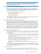
kilometers if Finisar (long haul) GBICs are used for the Inter Switch Links (ISL) between the Fibre Channel switches. WDM links can also be used for the connection between the Fibre Channel switches in the two Primary data centers and can provide ISL connections of up to 100 kilometers in length . • There must be at least two TCP/IP networking links, routed geographically differently between each Primary data center to prevent the “backhoe problem.
• The network switches can be 100Base T (TX or FX), 1000Base T (TX or FX), 10 Gigabit Ethernet. The connections between the network switches and the WDM boxes must be fiber optic. • Direct Fabric Attach mode must be used for the Fibre Channel switch ports connected to the WDM link. Redundant Fibre Channel switches are required in each data center, unless the switch offers built in redundancy. • Refer to the SWD Streams documents for supported Fibre Channel switches.
• Fibre Channel expects that the ordering of packets is preserved for the Inter switch links, however ordering is not guaranteed by SONET. Therefore, Fibre Channel Gateway / SAN Extension devices are typically used between the Fibre Channel switches and the SONET box to preserve the packet ordering. Redundant Fibre Channel switches are required in each data center, unless the switch offers built in redundancy. • Refer to the SWD Streams documents for supported Fibre Channel switches.
Volume Groups. Cluster lock disks are only supported for up to four nodes, therefore the cluster can contain only two or four nodes. • Mirrordisk/UX mirroring for Shared LVM volume groups is supported for EC RAC clusters containing two nodes. Using LVM version 2.0, which is available on HP-UX 11i v3, with SLVM volume groups is supported for EC RAC clusters containing two or four nodes. Refer to Figure 24 (page 49) for an example of two node Extended Distance Cluster configurations.
Refer to Figure 25 (page 64) for an example of an Extended Distance Cluster configuration in two data centers with a third location.
Figure 26 Extended Distance Cluster with Two Data Centers and DWDM Network Switch Network Switch DWDM Node A Node B DWDM Cluster Heartbeat Network and Storage Connections Data replication is being done with MirrorDisk/UX FC Switch Network Switch Network Switch DWDM DWDM Node C Node D FC Switch FC Switch FC Switch Cluster Lock Cluster Lock Maximum distance 100 kilometers Storage Site 1 Storage Site 2 In the figure 27, the alternate paths for both networking and Fibre Channel are config
Figure 27 Extended Distance Cluster Configuration with Two Data Centers and a Third Location with DWDM Links Arbitrator Third location Node E Node F Network Switch Network Switch DWDM e anc Dist um eters xim m Ma 0 kilo 10 Network Switch Network Switch Maxim um 100 kil Distance omete rs DWDM DWDM Node A Node B DWDM Network Switch Network Switch DWDM Redundant DWDM FC Switch DWDM Node C Node D FC Switch FC Switch FC Switch Storage Storage Primary Data Center 1 Maximum distance 100 kil
There can be up to 16 nodes in this cluster (this includes the nodes in the Arbitrator data center, unless they are running the Serviceguard Quorum Server). You can use SONET instead of DWDM in this configuration by replacing the DWDM boxes with SONET boxes. With SONET, you can use a point to point topology, as is shown in this example, or you can use a dual SONET ring topology which passes through all three data centers, where the working ring and the protection ring are alternately routed.
Serviceguard A.11.18 or before, or MEMBER_TIMEOUT period for Serviceguard A.11.19 and later). Cluster lock disks are not allowed in this configuration. There can be 2, 4, 6, or 8 nodes (and 10, 12, 14, or 16 with CVM 5.0 or 5.0.1 and Serviceguard A.11.19, SG SMS A.02.01, A.02.01.01 ,or SG SMS A.03.00) in this cluster if CVM or CFS is used and the distance is 10 kilometers or less. There can be only two nodes in this cluster, if CVM or CFS 4.1 is used and the distance is between 10 and 100 kilometers.
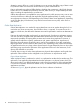
Figure 29 Extended Cross-Subnet Cluster with Two Data Centers and a Third Location with WDM Links QS Node Quorum Server Data Center Network Switch 1 Network Switch 3 Network Switch 2 Router 2 Network Switch 4 Router 3 WAN Router 1 Router 4 Cross Subnet Configuration DWDM Node A Node B FC Switch DWDM Storage Connections Redundant WDM Links frequently Node C Node D FC Switch FC Switch FC Switch Storage Primary Data Center 1 Maximum distance 100 kilometers Storage Primary Data Center 2
suggested) . There can be up to 16 nodes in this cluster and the maximum distance supported is 100 kilometers. You can use SONET instead of WDM in this configuration. With SONET, you could use a point to point topology, as shown in this example, or you can use a dual SONET ring topology which passes through the two Primary data centers, where the working ring and the protection ring are alternately routed. Additional information on Extended Distance Clusters is available at http://www.hp.
4 Comparison of Disaster Recovery Solutions Table 6 summarizes and compares the disaster recovery solutions that are currently available: Table 6 Comparison of disaster recovery Cluster Solutions Attributes Extended Distance Cluster Extended Distance Cluster Metrocluster for RAC (HP-UX only) Continentalclusters Key Benefit Excellent in “normal” operations, and partial failure.
Table 6 Comparison of disaster recovery Cluster Solutions (continued) Attributes Extended Distance Cluster Extended Distance Cluster Metrocluster for RAC (HP-UX only) Maximum Distance * 100 Kilometers * 100km (maximum is two nodes, with either CFS, SLVM or CVM) Continentalclusters Shortest of the distances No distance (up to 300km) restrictions. between: * 10km (maximum is two • Cluster network nodes with SLVM and latency (not to eight nodes with CVM exceed 200ms).
Table 6 Comparison of disaster recovery Cluster Solutions (continued) Attributes Extended Distance Cluster Extended Distance Cluster Metrocluster for RAC (HP-UX only) Client Client detects the lost Client may already have Transparency connection. You must a standby connection to reconnect after the remote site. application is recovered at second site. Maximum Cluster Size Allowed Client detects the lost connection. You must reconnect once the application is recovered at second site.
Table 6 Comparison of disaster recovery Cluster Solutions (continued) Attributes Extended Distance Cluster Extended Distance Cluster Metrocluster for RAC (HP-UX only) Continentalclusters or or Metrocluster 3PAR Remote Copy Metrocluster EMC SRDF or or Metrocluster EMC SRDF Toolkits for Data Replication solutions) On Linux: or Serviceguard for Linux+ Customer-selected Metrocluster with data replication Continuous Access XP subsystem P9000 for Linux CC with RAC using or CVM/CFS on HP-UX: Serviceguard
NOTE: For the most up-to-date support and compatibility information see the SGeRAC for SLVM, CVM and CFS Matrix and Serviceguard Compatibility and Feature Matrix on http://www.hp.com/ go/hpux-serviceguard-docs -> HP Serviceguard Extension for RAC. 1– The Cross Subnet feature is enabled beginning with Serviceguard A.11.18, and with appropriate patches on HP-UX . For more information on the Cross Subnet feature on Linux, see HP Serviceguard A.11.20.10 for Linux Release Notes available at www.hp.
Glossary A application restart Starting an application, usually on another node, after a failure. Application can be restarted manually, which may be necessary if data must be resynchronized before the application can run (example: Business Recovery Services work like this.) Applications can be restarted by an operator using a script, which can reduce human error. Or applications can be started on the local or remote site automatically after detecting the failure of the primary site.
cluster alert Time at which a message is sent indicating a problem with the cluster. cluster event A cluster condition that occurs when the cluster goes down or enters an unknown state, or when the monitor software returns an error. This event may cause an alert message to be sent out, or it may cause an alarm condition to be set, which allows the administrator on the Recovery Cluster to issue the cmrecovercl command.
disaster recovery architecture A cluster architecture that protects against multiple points of failure or a single catastrophic failure that affects many components by locating parts of the cluster at a remote site and by providing data replication to the remote site. Other components of disaster recovery architecture include redundant links, either for networking or data replication, that are installed along different routes, and automation of most or all of the recovery process.
Metrocluster A Hewlett-Packard product that allows a customer to configure an Serviceguard cluster as a disaster recovery metropolitan cluster. metropolitan cluster A cluster that is geographically dispersed within the confines of a metropolitan area requiring right-of-way to lay cable for redundant network and data replication components. mirrored data Data that is copied using mirroring. mirroring Disk mirroring hardware or software, such as MirrorDisk/UX.
planned downtime An anticipated period of time when nodes are taken down for hardware maintenance, software maintenance (OS and application), backup, reorganization, upgrades, and so on (software or hardware). PowerPath A host-based software product from Symmetrix that delivers intelligent I/O path management. PowerPath is required for M by N Symmetrix configurations using Metrocluster with EMC SRDF.
data, resulting in data corruption. Serviceguard architecture prevents split-brain syndrome in all cases unless dual cluster locks are used. SRDF (Symmetrix Remote Data Facility) A level 1-3 protocol used for physical data replication between EMC Symmetrix disk arrays. SVOL A secondary volume configured in an XP series disk array that uses Continuous Access. SVOLs are the secondary copies in physical data replication with Continuos Access on the XP.
Index A O asynchronous data replication, 10 offline data replication, 9 online data replication, 10 operations staff general guidelines, 19 C cluster extended distance, 49, 50, 54 cluster maintenance, 19 configuring, 15 disaster recovery Ethernet networks, 15 disaster recovery WAN, 16 consistency of data, 9 currency of data, 9 D data center, 7 data consistency, 9 data currency, 9 data recoverability, 9 data replication, 9 ideal, 13 logical, 12 offline, 9 online, 10 physical, 10 synchronous or asynchron