
HP Serviceguard Extended Distance Cluster for Linux A.11.20.10 Deployment Guide, December 2012
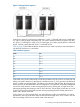


Table 4 Disaster Scenarios and Their Handling (continued)
Recovery ProcessWhat Happens When This
Disaster Occurs
Disaster Scenario
Complete the following procedure to initiate
a recovery:
1. Restore data center 1, Node 1 and
storage 1. Once Node 1 is restored, it
rejoins the cluster. Once S1 is restored,
it becomes accessible from Node 2.
When the package failed over and
started on Node 2, S1 was not a part
of md0. As a result, you need to add
S1 into md0. Run the following
command to add S1 to md0:
# mdadm – -add /dev/md0
/dev/hpdev/mylink-sde
The re-mirroring process is initiated.
When it is complete, the extended
distance cluster detects the added mirror
half and accepts S1 as part of md0.
2. Enable P1 to run on Node 1 by running
the following command:
# cmmodpkg -e P1 -n N1
The package (P1) fails over to
Node 2 and starts running with
the mirror of md0 that consists of
only the storage local to node 2
(S2).
A package (P1) is running on a node
(Node 1). The package uses a mirror
(md0) that consists of two storage
components - S1 (local to Node 1
-/dev/hpdev/mylink-sde ) and S2
(local to Node 2)
Data center 1 that consists of Node 1
and P1 experiences a failure.
NOTE: In this example, failures in a
data center are instantaneous. For
example - power failure.
For the first failure scenario, complete the
following procedure to initiate a recovery:
1. Restore the links in both directions
between the data centers. As a result,
S2 (/dev/hpdev/mylink-sdf ) is
accessible from N1 and S1 is accessible
from N2.
2. Run the following commands to remove
and add S2 to md0 on N1:
# mdadm --remove /dev/md0
/dev/hpdev/mylink-sdf
# mdadm --add /dev/md0
/dev/hpdev/mylink-sdf
The re-mirroring process is initiated. The
re-mirroring process starts from the
beginning on N2 after the second failure.
When it completes, the extended distance
cluster detects S2 and accepts it as part
ofmd0 again.
The package (P1) continues to run
on N1 after the first failure, with
md0 consisting of only S1.
After the second failure, the
package (P1) fails over to N2
and starts with S1. Since S2 is
also accessible, the extended
distance cluster adds S2 and
starts re-mirroring of S2.
This is a multiple failure scenario where
the failures occur in a particular
sequence in the configuration that
corresponds to figure 2 where Ethernet
and FC links do not go over DWDM.
The package (P1) is running on a node
(N1). P1 uses a mirror md0 consisting
of S1 (local to node N1,
say/dev/hpdev/ mylink-sde) and
S2 (local to node N2 ) .
The first failure occurs with all FC links
between the two data centers failing,
causing N1 to lose access to S2 and
N2 to lose access to S1.
After recovery for the first failure has
been initiated, the second failure occurs
when re-mirroring is in progress and
N1 goes down.
36 Disaster Scenarios and Their Handling