
Using Serviceguard Extension for RAC, 9th Edition, September 2010


5. Activate the volume group on one node in exclusive mode, then deactivate the volume
group:
# vgchange -a e vg_ops
This will synchronize the stale logical volume mirrors. This step can be time-consuming,
depending on hardware characteristics and the amount of data.
6. Deactivate the volume group:
# vgchange -a n vg_ops
7. Activate the volume group on all the nodes in shared mode using vgchange - a s:
# vgchange -a s vg_ops
Replacing a Lock Disk
Replacing a failed lock disk mechanism is the same as replacing a data disk. If you are using a
dedicated lock disk (one with no user data on it), then you need to issue only one LVM command:
# vgcfgrestore /dev/vg_lock /dev/dsk/c2t1d0
After doing this, wait at least an hour, then review the syslog file for a message showing that the
lock disk is healthy again.
Online Hardware Maintenance with Inline SCSI Terminator
Serviceguard allows online SCSI disk controller hardware repairs to all cluster nodes if you use
HP’s inline terminator (C2980A) on nodes connected to the end of the shared FW/SCSI bus. The
inline terminator cable is a 0.5 meter extension cable with the terminator on the male end that
connects to the controller card for an external bus. The inline terminator is used instead of the
termination pack that is attached to the controller card. The inline terminator makes it possible
to physically disconnect the node from the end of the F/W SCSI bus without breaking the bus's
termination. (Nodes attached to the middle of a bus using a Y cable also can be detached from
the bus without harm.) When using inline terminators and Y cables, ensure that all
orange-socketed termination packs are removed from the controller cards.
NOTE: You cannot use inline terminators with internal FW/SCSI buses on D and K series
systems, and you cannot use the inline terminator with single-ended SCSI buses. You must not
use an inline terminator to connect a node to a Y cable.
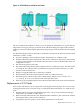
Figure 4-1 shows a three-node cluster with two F/W SCSI buses. The solid line and the dotted
line represent different buses, both of which have inline terminators attached to nodes 1 and 3.
Y cables are also shown attached to node 2.
126 Maintenance and Troubleshooting