
Cascading Failover in a Continentalclusters, December 2005
Introduction
Overview
Cascading failover is the ability for an application to fail from a primary to a secondary location, and
then to fail to a recovery location. The primary location, the primary and secondary site, contains a
metropolitan cluster built with the HP Metrocluster solution, and the recovery location as a standard
Serviceguard cluster. Continentalclusters provides a “push-button” recovery between Serviceguard
clusters. Data replication also follows the cascading model. Data is synchronously replicated from the
primary disk array to the secondary disk array in the Metrocluster, and periodically data is manually
replicated via storage data replication technology to the third disk array in the Serviceguard recovery
cluster.
Continentalclusters with cascading failover uses three main data centers distributed between a
metropolitan cluster, which serves as a primary cluster, and a standard cluster, which serves as a
recovery cluster.
In the primary cluster, there are two disk arrays, either of which can have the source volumes for a
particular application. Throughout this document, the term primary disk array refers to the disk array
that holds the volumes that are being replicated to the remote disk array for a particular application,
and the data center where this disk array is located is called the primary site. The term secondary disk
array refers to the disk array that holds the volumes that the data is being replicated to using the
storage specific replication technology for a particular application, and the data center where the
secondary disk array for that application is located is known as the secondary site. Thus, primary and
secondary sites are roles that can be played by either disk array in the primary cluster. However,
once the data replication link has been defined for the secondary disk array to the recovery disk
array, primary and secondary sites will be fixed.
The recovery disk array holds a remote replicated copy of the data in the recovery cluster. The data
center that houses the recovery disk array is called the recovery site. The data is replicated from the
secondary disk array to the recovery disk array through manual operations or custom made scripts.
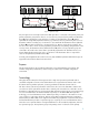
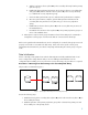
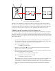
The basic design of the cascading failover solution is shown in Figure 1. The primary cluster, shown
on the left, is configured as a Metrocluster with three data centers physically located on three different
sites—two main sites (primary and secondary sites) and an arbitrator site (a third location) which is
not shown in the figure below. The primary and secondary sites can relative to the application given
that data replication is possible from both disk arrays in the primary cluster to the disk array in the
recovery cluster. A fourth data center (recovery site) is used for the recovery cluster, which is a
standard Serviceguard configuration. Also, the primary and recovery cluster are configured as a
Continentalclusters.
2