
Installation Guide, Fifth Edition - HP 9000 rp7420 Server


Chapter 4
Cabling and Power Up
MP Core I/O Connections
65
MP Core I/O Connections
Each HP 9000 rp7420 Server can have up to two MP Core I/O board sets installed. Which allows two
partitions to operate, or MP Core I/O redundancy in a single partition configuration. Each MP Core I/O board
set consists of two boards: the MP/SCSI board and the LAN/SCSI board. The MP/SCSI board is oriented
vertically and accessed from the back of the server. The LAN/SCSI is accessed from the PCI/PCI-X expansion
card bay. Only the primary MP core I/O board set (MP/SCSI slot 1 and LAN/SCSI slot 8, chassis 1) is required
for a single partition implementation. The secondary MP/SCSI board is not necessary for full operation;
however, without the secondary MP/SCSI board, only two internal disks can be accessed.
MP/SCSI Connections
The MP/SCSI board is required to update firmware, access the console, turn partition power on/off, access all
but two of the internal peripherals, and use other features of the system.
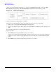
Connections to the MP/SCSI board include the following:
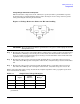
• DB25 Connector, by way of the M cable
This RS232 connector provides connections for a local console, external modem, and a UPS. The server
end of the M cable terminates in a DB25 connector. The opposite side of the cable terminates in three DB9
connectors labeled CONSOLE, UPS, and REMOTE.
• 10/100 Base-T LAN RJ45 connector (for LAN and Web Console access).
This LAN uses standby power and is still active if the front panel power switch is off and AC is present.
• Internal LVD Ultra 160 SCSI channel for connections to internal mass storage
• Internal SE Ultra SCSI channel for connection to an internal removable media device.
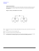
LAN/SCSI Connections
The LAN/SCSI board is a PCI form factor card that provides the basic external I/O connectivity for the
system.
Connections to the LAN/SCSI board include the following:
• PCI-X to PCI-X bridge for multi-device compatibility
• Internal LVD Ultra 160 SCSI channel for connections to internal mass storage
• External LVD Ultra 160 SCSI channel connected to a 68-pin VHDCI connector
• 10/100/1000 Base-T LAN RJ45 connector
The primary LAN interface is located on the LAN/SCSI board installed in the rightmost slot when viewing
the system from the back.
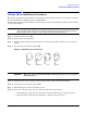
Management Processor Access
NOTE To access the Management Processor for the initial installation, the M cable must first be
connected to the DB25 connector located on the primary MP/SCSI board. The primary
MP/SCSI board is located in the lower MP/SCSI board slot.