
Installation Guide, Fifth Edition - HP 9000 rp7420 Server


Chapter 1
Introduction
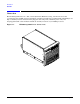
Detailed HP 9000 rp7420 Server Description
20
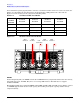
the board will not operate properly. There cannot be a terminator board in socket 1 or socket 3 locations. See
Table 1-2 for the CPU load order that must be maintained when adding CPUs to the cell board. See
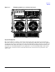
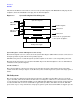
Figure 1-8 for the locations on the cell board for installing CPUs.
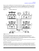
Figure 1-8 CPU Locations on Cell Board
DIMMs
Custom designed by HP, each DIMM contains 36 x 4 SDRAM memory components similar to PC-133 memory,
but qualified to run at 125 MHz. They have a low-voltage TTL interface. The CEC does not support
traditional DRAMs.
The HP 9000 rp7420 Server supports DIMMs with 256 MB, 512 MB 1 GB, and 2 GB capacity. Table 1-3 shows
each DIMM supported with its associated capacity, the resulting total system capacity, and the memory
component density.
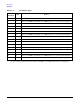
Table 1-2 Cell Board CPU Load Order
Number
of CPUs
Installed
Socket 0
Location
Socket 1
Location
Socket 2
Location
Socket 3
Location
Two CPU installed Empty slot Terminator Empty
Four CPU installed Empty slot CPU installed Empty
Six CPU installed CPU or Empty CPU installed Empty or CPU
Eight CPU installed CPU installed CPU installed CPU installed
Socket 2
Socket 3 Socket 1
Socket 0
CPU CPU CPU
CPU
Controller
Cell