
User Guide - rp5400 Family of Servers

4 Cable Connections
Core I/O Connections
The following paragraphs describe the indicators and connections of the rp54xx Core I/O. Core
I/O consists of a LAN/SCSI card in slot 1 (lower slot in graphic) and a Guardian Service Processor
(GSP) in slot 2 (upper slot in graphic). There are two versions of GSP, revision A and revision B.
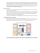
Revision A GSP
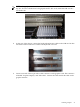
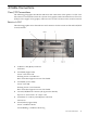
The following graphic shows the indicators and connectors for the revision A GSP and LAN/SCSI
Core I/O boards.
1. 10-Base-T LAN (RJ-45) Connector
GSP LAN.
2. Green/Red (Upper LED)
Green = GSP Power On.
Flashing Green = LAN Receive.
Red = Guardian Support Processor Test Failed.
3. Green/Red, (Lower LED)
Green = Link OK.
Flashing Green = LAN Transmit.
Red = Guardian Support Processor Test Failed.
4. Console/UPS/Remote Connector (D-Type 25-Pin female).
Requires an A5191-63001 "W" adapter cable
5. 10/100 Base-T = Primary LAN (RJ-45) Connection
Path 0/0/0/0
6. Green/Yellow (Upper LED)
Green = 100 Base-T Mode
Green Blinking = 100 Base-T Receiving
Core I/O Connections 45