
Carrier Grade Addendum - rp5400 Series of Servers


Chapter 1
Installation
Connecting the Server to DC Power Source
23
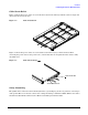
DC Power Cables
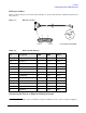
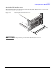
Figure 1-7 shows the power cable and connector. Table 1-3, “Power Cable Pinouts,” identifies the pinouts on
the connector.
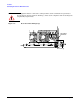
Figure 1-7 DC Power Cables
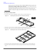
Connecting DC Power to High-Availability Systems
NOTE For complete power redundancy in high-availability systems, connect each power supply to
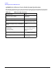
Table 1-3 Power Cable Pinouts
J1 Description AWG
MM
2
Color
Shield GND
A1 -48 VDC (A) 12 3.31 Black
A2 RTN (A) 12 3.31 White
A3 -48 VDC (B) 12 3.31 Red
A4 RTN (B) 12 3.31 Green
Case Shield GND
1 ALARM SET 22 .326 Black
2 PS WARN CL 22 .326 White
3 RMT PWR OFF CL 22 .326 Red
4 VINA FLT CL 22 .326 Green
5 VINB FLT CL 22 .326 Orange
6 PS FLT CL 22 .326 Blue
J1
1
A2A1 A3 A49
10
11
Part Number Z7535-63002